[0006] The present invention relates to systems and methods for the multifocal imaging of
biological materials. An optical
system is provided in which a plurality of optical pathways are used in combination with focusing
optics to provide a plurality of focal locations within a
region of interest of a material being optically measured or imaged. The
detector can comprise a plurality of
detector elements which are correlated with the plurality of focal locations to provide for the efficient collection of light from the material being imaged. A preferred embodiment of the invention utilizes a scanning system that provides relative movement between the material and the focal locations to provide for fast imaging of the material.
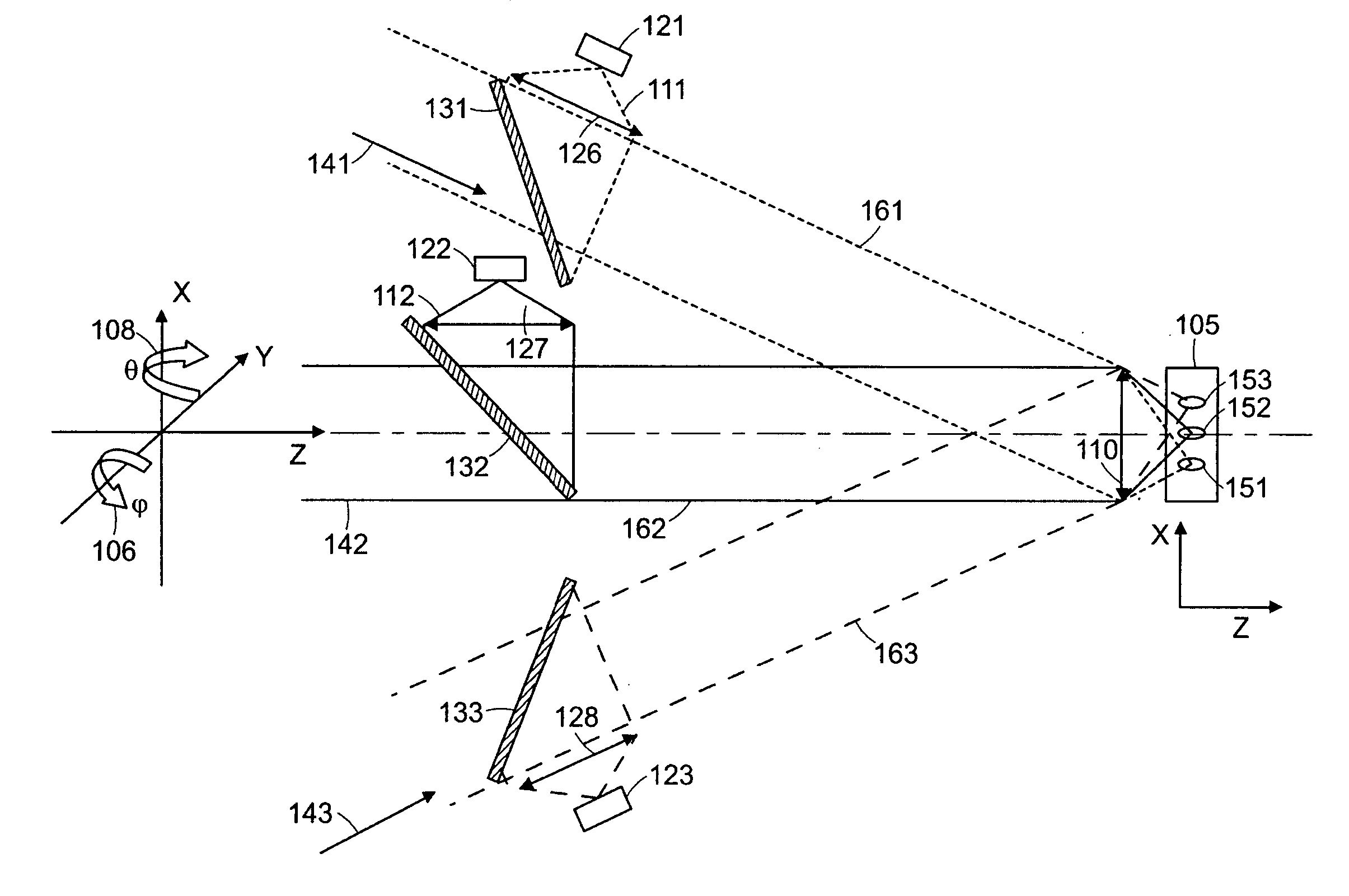
[0008] An important issue in the collection of light from discrete focal spots or locations within a turbid medium such as tissue is the cross talk that can occur due to the scattering of light. This cross talk can substantially limit the usefulness of the images of the tissue that are produced. By increasing the distance between adjacent focal spots such cross talk can be reduced or eliminated, however, this reduces the resolution of the resulting image or increases the time needed to scan the tissue. Thus it is desirable to employ focal spacing of at least 10 microns and preferably more than 25 microns.
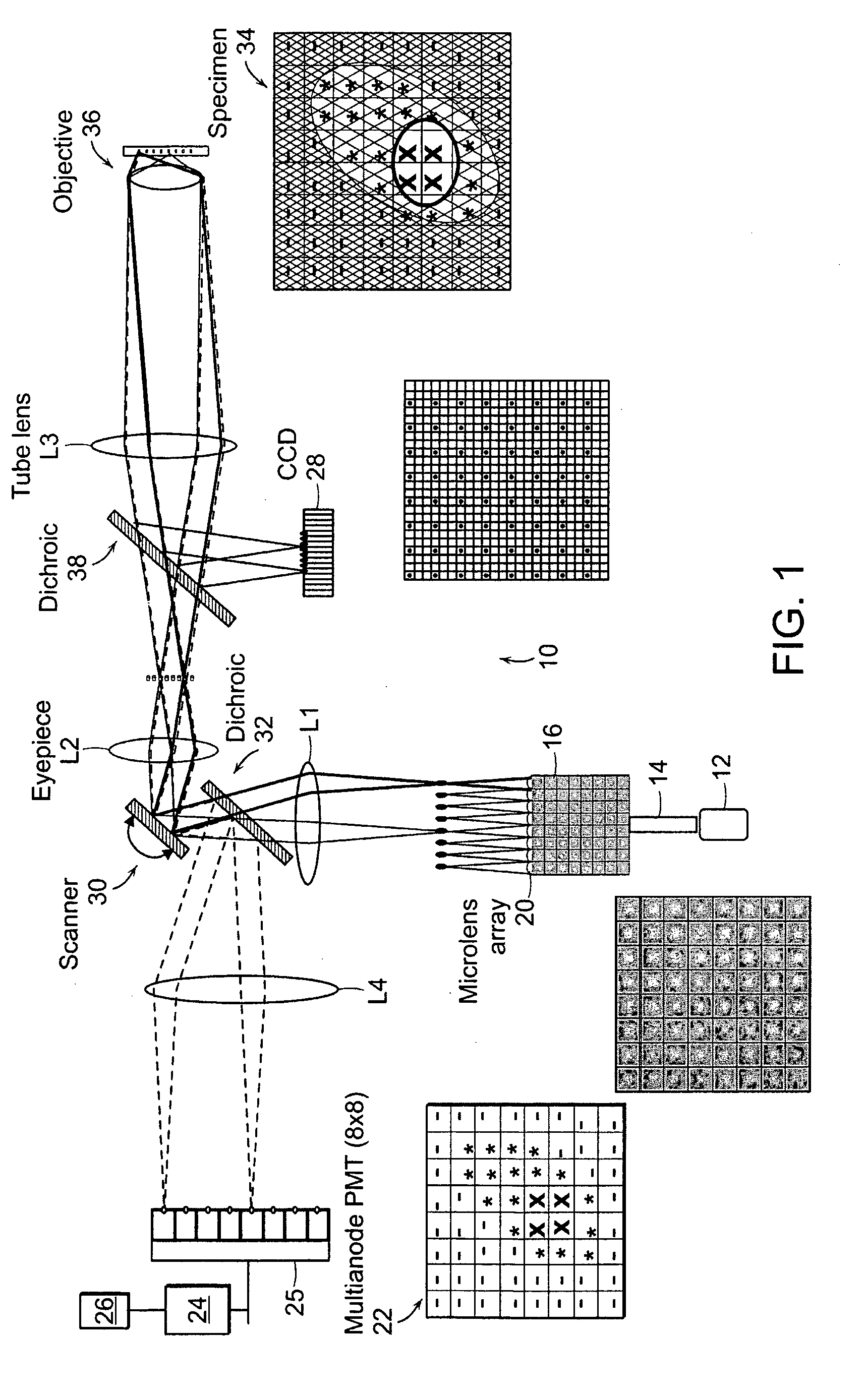
[0010] Systems and methods have been developed to enhance
multiphoton imaging speed. A first method increases the scanning speed by using a high-speed
scanner such as a polygonal mirror
scanner or a resonant mirror
scanner instead of a
galvanometer-driven mirror scanner. This achieves an increase of scanning speed of more than 10 frames per second in the imaging of typical tissue specimens. In general, the system can operate at frequencies in a range of 1 to 500 Hz. This method can be used for turbid
tissue imaging since it is not sensitive to the scattering of emission photons. A second method increases the imaging speed by parallelizing the
multiphoton imaging process. It scans a sample with a multiple of excitation foci instead of forming only a single focus. These foci are raster scanned across the specimen in parallel where each focus needs to cover a smaller area. The emission photons from these foci are collected simultaneously with a
spatially resolved detector. One
advantage of this method is that the imaging speed is increased by the number of excitation foci generated, without increasing the power of excitation light per each focus. High speed scanning systems needs
higher power to compensate for the
signal reduction per pixel due to the decrease of pixel dwell time. Images can be obtained by selecting the
depth of focus to be positioned in a plane within the tissue or sample at a depth in a range of 10 microns to 500 microns.
[0012] The brain is an inherently three dimensional organ composed of many subregions.
Accurate segmentation of brain morphology of small mammals is currently challenged by the lack of techniques which can sample the brain at
high resolution over a large volume. The current method of choice,
serial section reconstruction, is laborious,
time consuming, and error prone. The device and methods described herein can quickly image brains or thick
tissue sections of brains in 3D at sufficient resolution and over a large enough volume to provide 3D images suitable for classification of brain morphology and
biochemical composition. The brain can be further stained by dyes, such as nuclear dyes
DAPI or Hoescht, either through intravital injection, transgenic expression, or
ex vivo methods, to facilitate classification of regions.
Automatic segmentation routines can also be used to improve the classification and automate portions of the process.
[0013] Accurate measurement of vasculature is important to characterize many biomedical for vasculature related diseases. For instance, proangiogenesis therapies are useful in such areas as
tissue engineering,
wound healing, bone fractures and
coronary heart disease. Anti-angiongenesis treatments are important in processes as
cancer,
blindness, and
rheumatoid arthritis. Unfortunately traditional histopathological analysis of
tissue sections is wholly inadequate to characterize the vasculature of a tissue or organ as blood vessels form complex, multiscale 3D networks, with feature spanning from the submicron to
centimeter scale. The device and methods described in the patent are capable of acquiring high quality 3D datasets over 3D tissue and organ samples suitable for characterization of the vasculature of the tissue. To aid
visualization of the vasculature, the tissue can be stained by contrast agents which bind to the epithelial wall of the blood vessels, or fill the interior of vessels.
Automatic segmentation routines can also be used to improve the classification and automate portions of the process.
[0014] A large percentage of deaths are due to
metastasis. Unfortunately, the migration of
cancer cells from the
primary tumor to secondary sites is a multi-step process which is not well understood. Standard histopathological analysis is ill-suited to study
metastasis and suffers from a number of limitations. First, it is extremely difficult to find rare metastatic
cancer within a 3D bulk tissue using traditional 2D
histopathology. In many instances traditional 2D
histopathology is unable to find evidence of the presence of metastatic cancer cells in an organ of animal. However, it is known that many subjects eventually develop tumors at a later time. It is clear that traditional
histopathology cannot effectively detect rare cells. Another limitation is that the present histopathology methods provide limited information about the 3D spatial arrangement of cancer cells with the 3D vasculature of the organ. It is known that one of the critical steps in
metastasis is
extravasation into the surrounding stroma from the vasculature so it is essential to be able to visualize this
spatial relationship between
cancer cell and the endothelial
blood vessel wall. Preferred embodiments of the present invention are capable of acquiring high quality 3D datasets over 3D tissue and organ samples suitable for characterization of the metastases. To aid
visualization of the metastases, the
cancer cell can be stained by dyes or labeled with proteins such as OFP.
Automatic segmentation routines can also be used to improve the classification and automate the localization of the cancer cells and tumors.

