Method and apparatus for directly cooling hollow conductor wound transverse gradient coil boards

a transverse gradient coil and coil board technology, applied in the field of mri systems, can solve the problems of inefficient heat conduction, material temperature limitation, and high current level of conventional gradient coils, and achieve the effects of improving thermal efficiency, improving image quality, and improving thermal efficiency

Inactive Publication Date: 2005-02-17
GE MEDICAL SYST GLOBAL TECH CO LLC
View PDF23 Cites 60 Cited by
  • Summary
  • Abstract
  • Description
  • Claims
  • Application Information

AI Technical Summary

Benefits of technology

[0007] Another object of the present invention is to improve the thermal efficiency of the MRI. It is a further object of the invention to provide a device having better image quality and the ability to scan images more quickly. It is yet a further object of the present invention to provide for a transverse gradient coil that permits passage of larger currents and voltages. It is yet a further object of the present invention to provide a device that enables new scanning protocols such as fMRI and coronary artery imaging. The improved thermal efficiency also improves product reliability by avoiding thermally induced failures. It is also an object of the present invention to provide a cooling system for use with “flat” gradient coils, such as may be used in an open architecture MRI.
[0008] The present invention has obtained these objects. It increases the thermal efficiency of MRI, improves imaging quality by reducing homogeneity variations due to temperature fluctuations and improves product reliability by reducing thermally related failures. The present invention also permits that passage of larger currents, thereby increasing magnetic field strength and image quality.

Problems solved by technology

In the resonance module, there are material temperature limitations such as the glass transition temperature.
High current levels employed in conventional gradient coils produce significant heat proximate to the coil.
The space between the active circuits and the water pipes is usually of material with good insulation properties, such as fiberglass, making heat conduction inefficient.
The resulting heat generation puts thermal limits on the operation of the coil.
These demands are driving up operating currents and voltages.
The increases in operating currents are generating additional heat loads surpassing the ability of existing thermal systems.

Method used


Image

  • Method and apparatus for directly cooling hollow conductor wound transverse gradient coil boards
  • Method and apparatus for directly cooling hollow conductor wound transverse gradient coil boards
  • Method and apparatus for directly cooling hollow conductor wound transverse gradient coil boards

Examples


Embodiment Construction

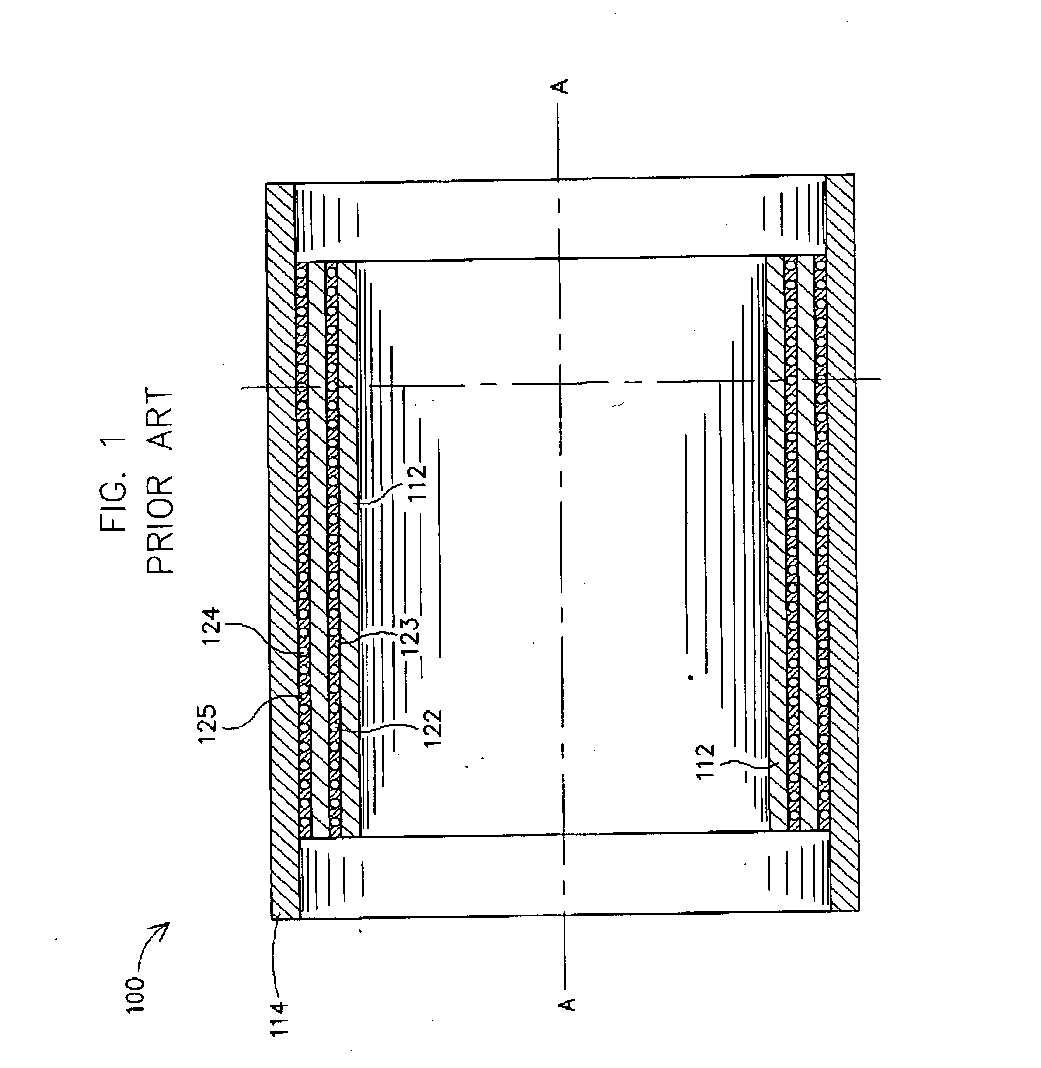
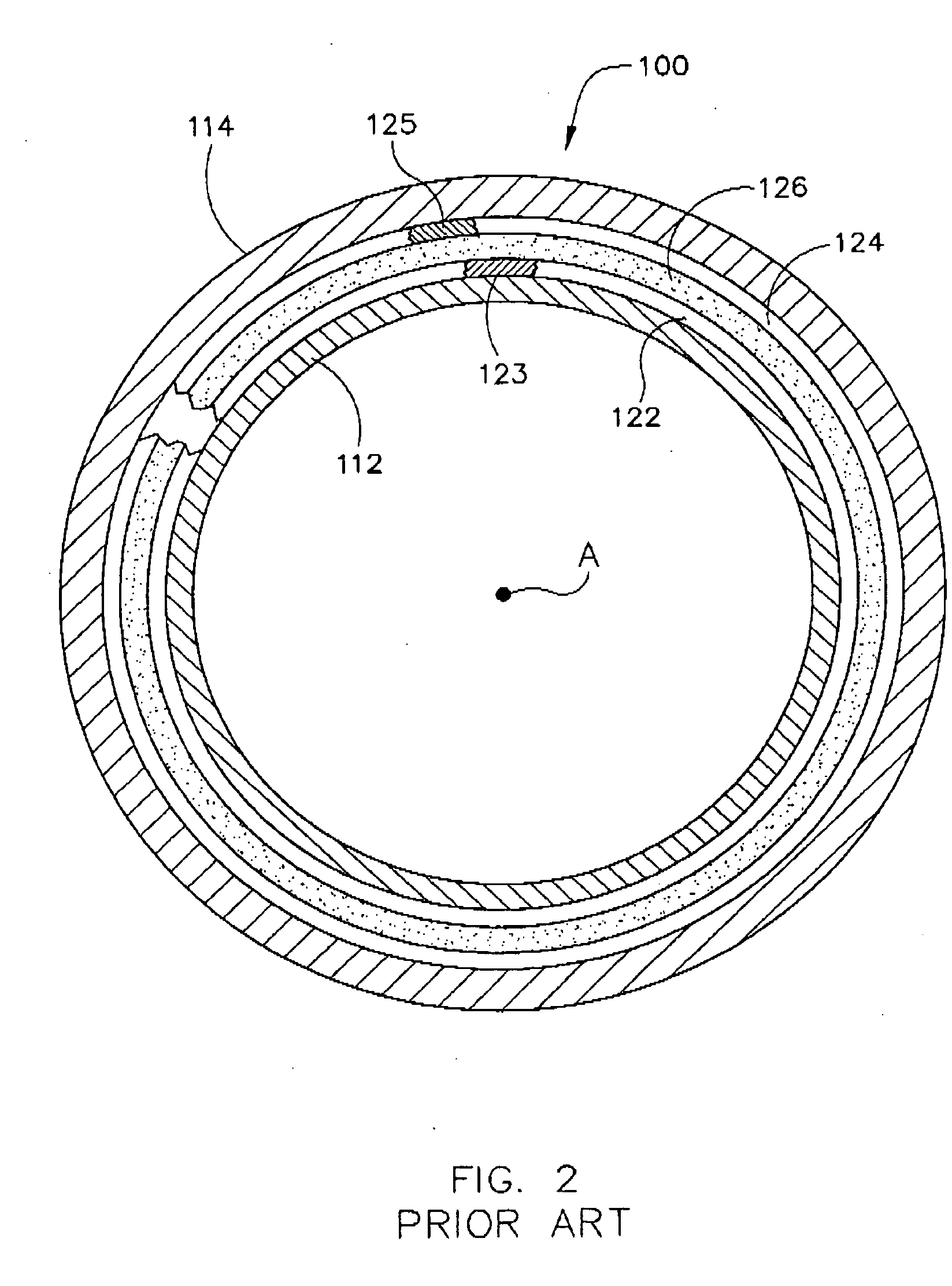
[0015]FIGS. 1 and 2 show a self-shielded gradient coil assembly 100 for an MR imaging system (not shown), comprising cylindrical inner and outer gradient coil windings 112 and 114, respectively, disposed in concentric arrangement with respect to common access A. A continuous cooling tube 122 is wound in a helix of the outer diameter surface of inner gradient coil winding 112 and a corresponding continuous cooling tube 124 is formed in a helix in the inner diameter surface of outer gradient coil winding 114, tubes 122 and 124 being respectively held in place by layers of epoxy 123 and 125. Inner gradient coil winding 112 includes inner coils of x-, y-, and z-gradient coils pairs, or sets, and outer gradient coil winding 114 includes the respective outer coils of the x-, y-, and z-gradient coil pairs or sets. Inner and outer gradient coil windings 112 and 114 are held in radially spaced apart coaxial relationship, relative to each other by annular end rings (not shown) which may be fi...


PUM


Abstract

MRI operates by passing current through gradient coils to create a magnetic field. Creation of the magnetic field requires a relatively high current which causes a large heat build up within the MRI, especially in the patient space. The present invention provides for a hollow conductor through which a coolant can be passed directly during the application of current.

Description

BACKGROUND OF INVENTION [0001] The present invention relates generally to magnetic resonance imaging (MRI) systems, and more particularly, to an assembly and method to dissipate the heat generated by transverse gradient coil boards that are used in an MRI. [0002] When a substance such as human tissue is subjected to a uniform magnetic field (polarizing field B0), the individual magnetic moments of the spins in the tissue attempt to align with the polarizing field, but precess about it in random order at their characteristic Larmor frequency. If the substance, or tissue, is subjected to a magnetic field (excitation field B1) which is in the x-y plane and which is near the Larmor frequency, the net aligned moment, or “longitudinal magnetization”, Mz may be rotated, or “tipped”, into the x-y plane to produce a net transverse magnetic movement Mt. A signal is emitted by the excited spins after the excitation signal B1 is terminated and this signal may be received and processed to form a...

Claims


Application Information

Patent Timeline
Patent Type & Authority Applications(United States)
IPC IPC(8): A61B5/055G01R33/385G01R33/389
CPCG01R33/3856
Inventor MANTONE, ANTHONYCLARKE, NEILDUBY, TOMASLIU, QINSELLERS, MICHAEL B.
Owner GE MEDICAL SYST GLOBAL TECH CO LLC
Why Eureka
Try Eureka