Solar power plant and method and/or system of storing energy in a concentrated solar power plant

a solar power plant and concentrated technology, applied in steam engine plants, machines/engines, propulsion parts, etc., can solve the problems of the rest of the power plant becoming extremely expensive to operate at such high temperatures, and achieve the effects of short heating time, low pressure drop, and high thermal conductivity

Active Publication Date: 2010-07-15
RES FOUND THE CITY UNIV OF NEW YORK
View PDF11 Cites 72 Cited by
  • Summary
  • Abstract
  • Description
  • Claims
  • Application Information

AI Technical Summary

Benefits of technology

[0049]The total efficiency of storage should be over 90% preferably over 95% and most preferably over 97%. However, as long as the efficiency is over 90%, the storage according to the invention still has a large efficiency advantage over present liquid storage media, despite the fact that the latter has a much lower energy requirement for pumping. Due to the strong temperature restrictions, the overall efficiency is significantly lower (by 10 to 30%) than feasible with compressed gas even for present designs). A big advantage of the invention is therefore that it can store heat instead of a heat transfer fluid and can be designed to operate well at temperatures up to 3000° F. however due to material constraints, the rest of the system limits the temperature to below 2000° F. and in some cases to below 1700
[0050]While the solid filling can vary (e.g., size, quantity, type, etc.), it preferably provides a uniform flow distribution through the media and minimizes pressure drops. Furthermore, the time required to heat or cool a particle or an element of the solid filling should be short compared to the residence time of the compressed gas in the tank(s) preferably smaller by at least a factor of 10 and most preferably, by a factor of 20 or more. Accordingly, solid fillings having a high thermal conductivity (at least 2 W / m° K., preferably larger than 5 W / m° K. and, most preferably larger than 15 W / m° K.) such as alumina, are preferable. A relatively short heating time and a good flow distribution are required to ensure that the heat deposited will progress as a narrow front along the length of the tank(s).
[0051]The tank(s) should be sufficiently long that the cool end remains cool at the end of the heat storage cycle. The same would apply when the flow is reversed. The hot end should still stay hot until the end of the heat recovery cycle. The capacity of the heat storage tanks should be sufficient to accommodate the maximum volume of storage needed. Thus, it should cover the case of maximum solar insolation and provide a spare capacity for variation of solar insolation during different days or maybe an extra day or two for bad weather. The maximum total output during the day is still limited by the size of the solar thermal collectors, unless the heat storage is for multiple days.
[0052]The concept and design of the heat storage system is a critical part of the invention. It is based on the principle of a recuperative heat exchanger, which has been used for more than eighty years to improve the thermal efficiency of power plants by heat exchanging the hot flue gas with the fresh air fed to the combustor. The same principle was used more recently in the development of cyclic catalytic reactors (Matros, Y. S. H., and Bunimovich, G. A.; “Reverse Flow Operation in Fixed Bed Catalytic Reactors”, Catal. Rev.—Sci. Eng., 38 (1), 1-63 (1996). This reference gives detailed instructions for designing the recuperative heat exchanger part of the reactor such that the heat propagates with a narrow front.
[0053]For the recuperative heat exchanger and the cyclic catalytic reactor, the cycles are of equal duration and the gas velocities are also equal in both directions. With our invention, after the storage cycle the hot tank is kept warm for longer periods for the purpose of storing heat and no flow occurs during this time. While the heat is recovered, the flows may differ completely from those which occur during the storage period as they are dictated by the needs of the power plant. Thus, while our invention uses the same concept for both heat propagation and recovery as the recuperative heat exchanger and the cyclic catalytic reactor, the heat storage system is a significantly more flexible and novel system. Not only are the vessels larger, but also there is no relation between the flow velocity and cycle times between storage and recovery. As in load following, the velocities would be much higher during recovery than during storage and would vary with time. Also during storage, the sunshine varies and therefore the flow to the storage tank varies while the temperature of the gas going to the collectors is kept constant. All these factors have to be taken into consideration for effective design to assure that the heat is recovered with no temperature loss.
[0054]The size of the power plant is determined by the maximum daily load expected, and the maximum output desired for purposes of control. The examples given below, including the choices for the design parameters and the solar insolation, are just realistic illustrative non-limiting examples. The advantage of a concentrating solar power plant utilizing heat storage system HSS is that the solar thermal collectors of system CSTC and the power plant PP can be designed independently to meet a desired control and delivery schedule.

Problems solved by technology

While the design of the storage tank and the potential fillers allow storage temperatures up to 3000° F., the rest of the power plant becomes extremely expensive to operate at such high temperatures.

Method used


Image

  • Solar power plant and method and/or system of storing energy in a concentrated solar power plant
  • Solar power plant and method and/or system of storing energy in a concentrated solar power plant
  • Solar power plant and method and/or system of storing energy in a concentrated solar power plant

Examples


example 1

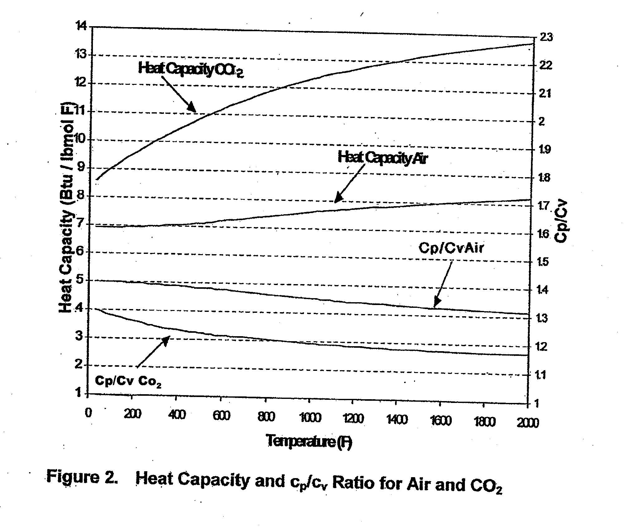
[0066]The first example illustrates a concentrating solar power plant for supplying intermediate load and will be described with reference to Tables 1 to 4. Consider the example of a concentrating solar power plant of 100 MWe rated capacity built in a sunny desert region. The total plant is not dealt with. Instead, only the elements related to heat storage are considered. The results for both air and CO2 as heat transfer medium (see Table 2) are, however, provided. It is further assumed that the power plant PP is designed to deliver 13 hours a day at a guaranteed capacity of 100 MWe (see Table 1). For purposes of control, the steam power plant PP is designed for 150 MWe to allow for fluctuations in demand and the higher output in the summer months. On the other hand, the total daily output is limited by the size of the solar thermal collectors of the system CSTC and heat storage capacity of the system HSS. As in any other storage system, there are design considerations which strongl...

example 2

[0074]The second example illustrates a concentrating solar power plant to supply to a grid with instantaneously dispatchable electricity in order to compensate for rapid changes in the load. The grid faces large changes in demand during short periods. New alternative energy sources such as wind and solar cells have introduced a new variability to the grid, as they are not constant and vary with the time of the day and the weather. While energy storage for them is feasible, available storage methods (batteries, compressed air, etc.) have a cost of above 20 cents / kWh stored, a factor of 10 higher than the method and system described herein, and energy losses of 20-25%. Using the invention, the cost of the storage is less than 2 cents / kWh and the energy losses are less then 5%. For example, in a year, 7 hours of storage a day provide 2555 hours of stored electricity. If we apply a capital charge of 10% per year, this gives $40-42 per year or about 1.6 cents / kWh. Even at double the inve...


PUM


Abstract

A method for storing heat from a solar collector CSTC in Concentrating Solar Power plants and delivering the heat to the power plant PP when needed. The method uses a compressed gas such as carbon dioxide or air as a heat transfer medium in the collectors CSTC and transferring the heat by depositing it on a bed of heat-resistant solids and later, recovering the heat by a second circuit of the same compressed gas. The storage system HSS is designed to allow the heat to be recovered at a high efficiency with practically no reduction in temperature. Unlike liquid heat transfer media, our storage method itself can operate at very high temperatures, up to 3000° F., a capability which can lead to greater efficiency. Due to material constraints and cost considerations in the rest of the system the maximum temperature is presently limited to between 1700° F. and 2000° F. The method can be applied to all current solar collector designs. This Abstract is not intended to define the invention disclosed in the specification, nor intended to limit the scope of the invention in any way.

Description

CROSS-REFERENCE TO RELATED APPLICATIONS[0001]The present application claims the benefit of U.S. Provisional Patent Application No. 60 / 905,729, filed on Mar. 8, 2007 under 35 U.S.C. §119(e), the disclosure of which is expressly incorporated by reference herein in its entirety.BACKGROUND OF THE INVENTION[0002]1. Field of the Invention[0003]The invention relates to a system and method of storing heat in a concentrating solar power plant. The system can use a compressed, preferably non-flammable gas, e.g., air or carbon dioxide (CO2), as the heat transfer medium.[0004]Also, according to the invention, a large number of solar thermal collectors can be arranged in a row and the gas is passed through them at high velocity. As sunshine is not constant but the demand for electricity is ongoing, the solar thermal collectors are large enough to produce the desired total power output per day. During peak periods of sunshine, the heated gas from the solar thermal collectors is passed to the powe...

Claims


Application Information

Patent Timeline
Patent Type & Authority Applications(United States)
IPC IPC(8): F02B63/04F24J2/34F03G6/00F02C6/00F24S90/00
CPCF03G6/04F24J2/07F24J2/42F28D20/0056F28D2020/006Y02E10/41F22B1/006Y02E60/142Y02E70/30F28D17/005F28D2020/0047Y10S165/902Y02E10/46F24S90/00F24S20/20Y02E60/14Y02T10/7072Y02E10/40
Inventor SHINNAR, REUEL
Owner RES FOUND THE CITY UNIV OF NEW YORK
Why Eureka
Try Eureka