Respiratory breathing devices, methods and systems

a technology of respiratory breathing and breathing device, which is applied in the direction of respirator, valve, operating means/releasing device, etc., can solve the problems of cumbersome and time-consuming, changes in air delivery requirements of papr system, and change in air delivery requirements

Inactive Publication Date: 2009-10-29
MINE SAFETY APPLIANCES CO +1
View PDF12 Cites 118 Cited by
  • Summary
  • Abstract
  • Description
  • Claims
  • Application Information

AI Technical Summary

Benefits of technology

[0019]The present invention provides significant advantages over currently available powered air purifying systems by, for example, controlling the motorized blower thereof on the basis of a determined resistance to flow of a sensed PAPR configuration, including determination of the type of filter system(s) incorporated into the PAPR system. Sufficient air flow is provided without substantial risk of excessive air flow rates which are associated with user discomfort, excessive battery consumption and excessive component (including, for example, motor) wear. Moreover, the PAPR devices, systems and methods of the present invention are the first to control operation at least in part on the basis of information related to measured ambient pressure.

Problems solved by technology

Moreover, changes within the PAPR system as a result of operation over time can also cause changes in air delivery requirements of a PAPR system.
For example, filter loading, blockage, component wear, frictional increases, and battery power loss can individually and collectively cause changes in air delivery requirements.
Although a number of calibration and control systems and methods are used in connection with PAPR systems, a number of problems are associated with currently available PAPR systems and the methods of operation thereof.
For example, calibration may require at least partial disassembly of the PAPR system, which can be cumbersome and time consuming, particularly while in the field.
Moreover, many calibration and control systems and methods can consume significant power, resulting in reduced battery life.
For example, PAPR systems are often calibrated and controlled to provide sufficient air flow for the configuration providing the highest resistance to flow, resulting in air flow rates higher than desirable, excess power consumption and excess motor wear in connection with configurations with lower resistance.
Further, currently available PAPR systems do not adequately address change in operation of the system as a result of ambient pressure change (for example, as a result of altitude changes).

Method used


Image

  • Respiratory breathing devices, methods and systems
  • Respiratory breathing devices, methods and systems
  • Respiratory breathing devices, methods and systems

Examples


Embodiment Construction

[0032]As used herein and in the appended claims, the singular forms “a,”“an”, and “the” include plural references unless the content clearly dictates otherwise. Thus, for example, reference to “a sensor” includes a plurality of such sensors and equivalents thereof known to those skilled in the art, and so forth, and reference to “the sensor” is a reference to one or more such sensor and equivalents thereof known to those skilled in the art, and so forth.

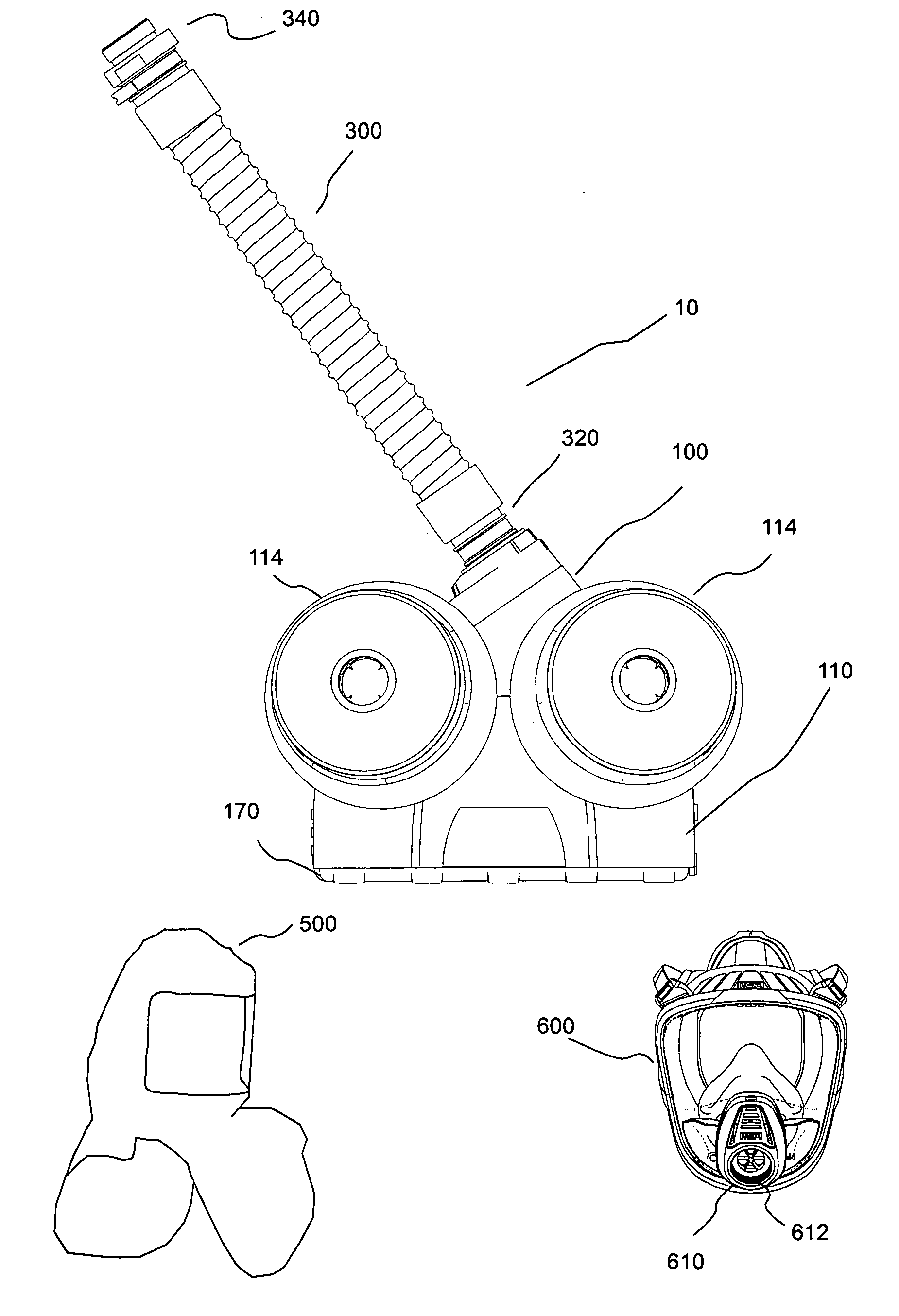
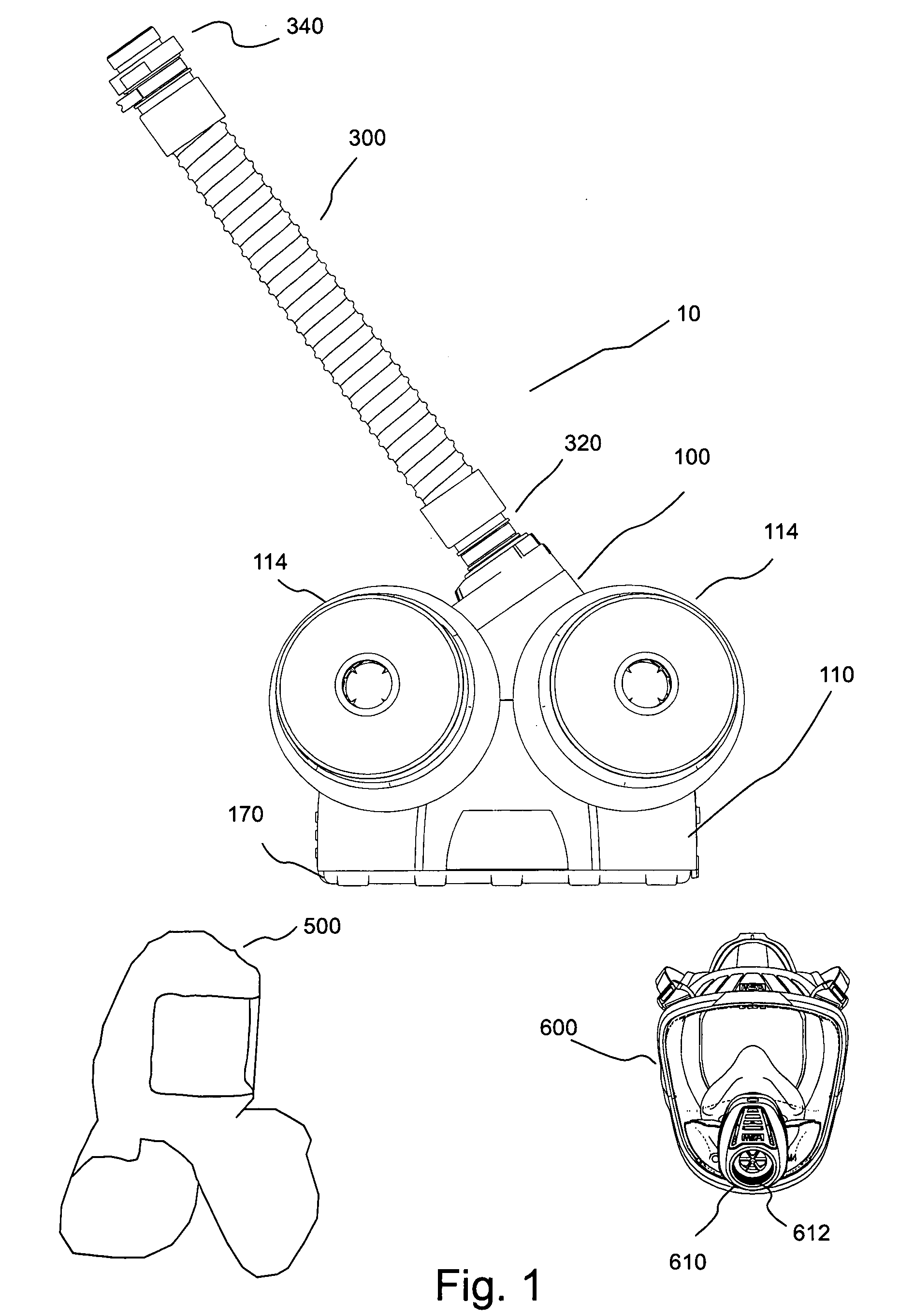
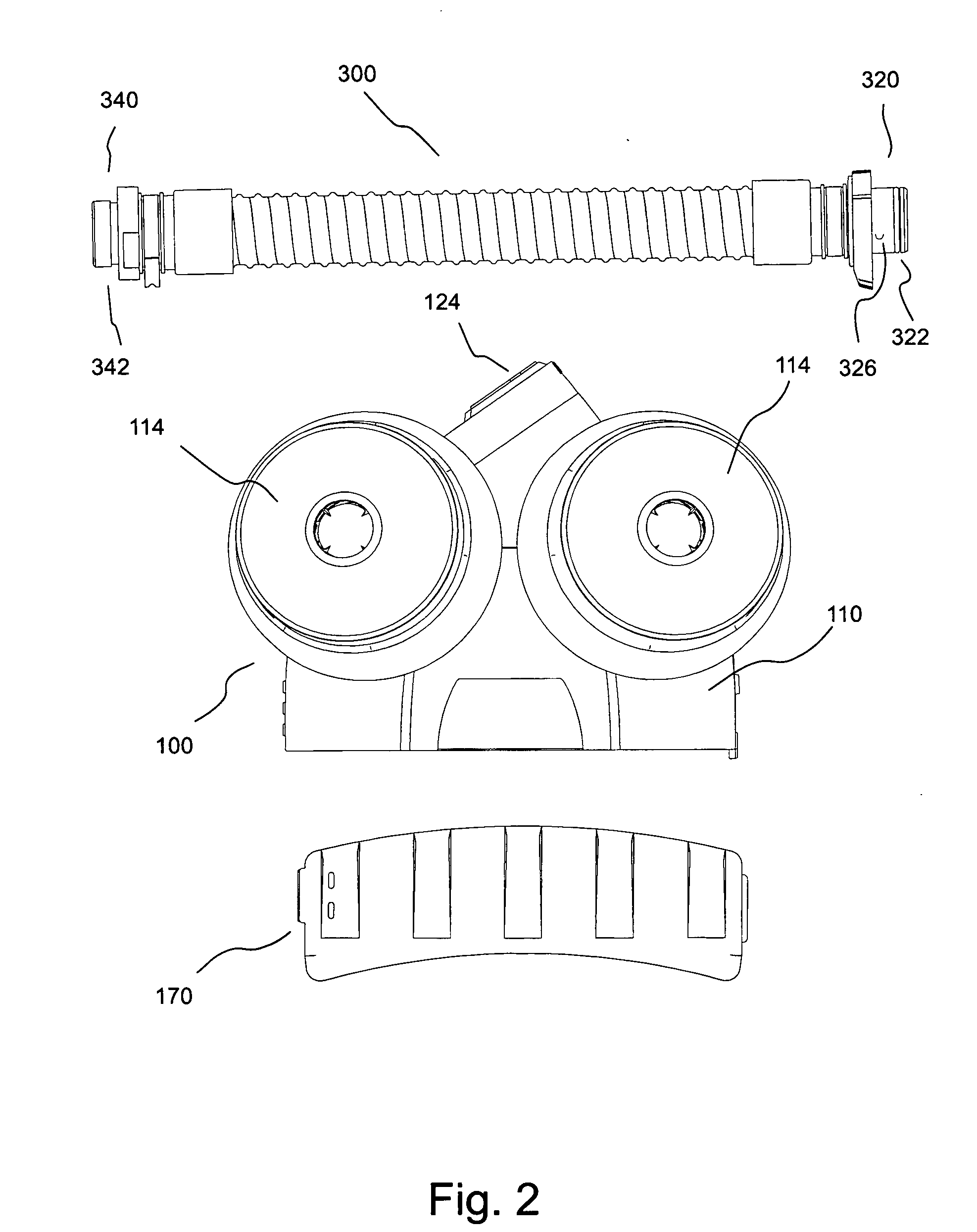
[0033]FIGS. 1 through 10B illustrate an embodiment of an air delivery or PAPR system 10 of the present invention. Air delivery system 10 includes blower assembly 100 in fluid connection with a delivery tube or hose 300. As illustrated, for example, in FIG. 2, delivery hose 300 includes a first connector 320 for connection to an outlet 124 of a scroll housing 120 (see FIG. 6) of blower assembly 100 and a second connector 340 for connection to a user worn component or respiratory inlet covering such as a hood 500 or a mask 600 (see FIG...


PUM


Abstract

A powered air purifying respirator system for use with at least one filter system includes: a housing including at least one inlet port and at least one outlet port; a motorized air flow system to draw air into the housing via the at least one inlet port; a control system in communicative connection with the motorized air flow system; and a filter system sensor in communicative connection with the control system. The filter system sensor provides information to the control system relating to the type of the at least one filter system upon fluid connection thereof with the housing. The control system can control the motorized air flow system at least in part on the basis of the type of filter system sensed by the filter system sensor. Another powered air purifying respirator system for use with at least one filter system includes: a housing including at least one inlet port and at least one outlet port; a motorized air flow system to draw air into the housing via the at least one inlet port; a control system in communicative connection with the motorized air flow system; and a pressure sensor in communicative connection with the control system to provide information to the control system relating to ambient pressure. The control system can, for example, control the motorized air flow system at least in part on the basis of the information relating to ambient pressure.

Description

BACKGROUND OF THE INVENTION[0001]The present invention relates to respiratory breathing devices, systems and methods and, particularly to Powered Air-Purifying Respiratory breathing devices, systems and methods.[0002]The following information is provided to assist the reader to understand the invention disclosed below and the environment in which it will typically be used. The terms used herein are not intended to be limited to any particular narrow interpretation unless clearly stated otherwise in this document. References set forth herein may facilitate understanding of the present invention or the background of the present invention. The disclosure of all references cited herein are incorporated by reference.[0003]There are a number of respiratory breathing systems commercially available to protect people from a variety of respiratory hazards. One type of respiratory breathing system, commonly referred to as Powered Air-Purifying Respirator systems or PAPR systems, uses a powered...

Claims


Application Information

Patent Timeline
Patent Type & Authority Applications(United States)
IPC IPC(8): A62B7/00
CPCA62B18/006A62B7/10
Inventor BILGER, ADAM S.WOLF, ROGER P.PANIAN, THOMAS L.CATANZARITE, MARTIN S.
Owner MINE SAFETY APPLIANCES CO
Why Eureka
Try Eureka