Guidewire support catheter

a technology of support catheter and guidewire, which is applied in the field of guidewire placement and support catheter, can solve the problems of affecting the function of the guidewire, debilitating and life-threatening, and other complications, and achieves the effects of preventing damage to the lumen of the vessel, facilitating control, and improving engagemen

Active Publication Date: 2010-10-28
AVINGER
View PDF100 Cites 120 Cited by
  • Summary
  • Abstract
  • Description
  • Claims
  • Application Information

AI Technical Summary

Benefits of technology

[0036]As mentioned briefly above, various aspects of the devices described herein provide substantially benefits compared to other device which may be used in occluded vessels, including rotating devices. For example, the forward cutting blades may prevent cutting on the sides / walls of the lumen. This configuration may also help with self-centering, as mentioned. In addition, the device may be configured so that the diameter of the blade (e.g., wedge) region is the same as the diameter of the rest of the catheter. Thus, the diameter of the distal end having the rotatable wedge is maxed out, so that the blades are as big across as the rest of the catheter, which may allow for maximum traction in the lumen of the vessel. The diameter of the blades (the distal region including the blade or blades) may therefore be equal to the diameter of the catheter. This in turn may allow the blades to engage better with the tissue of the vessel because there is more region of the vessel (e.g., width) available for the blade to engage with.
[0037]As mentioned, the distal end region may be rotated manually. For example, the tip may be spun or rotated by rotating a control or portion of the proximal handle. Thus, the device may be used as a screwdriver or drill element that is manually turning at a slow, more controlled (e.g., continuously and manually variable) rate. This may also provide tactile feedback to the operator, who can gauge how much force is applied by the feel of the device. For example, a clinician may determine how much force to apply both to advance and to spin the blades. Compared to true “drilling” elements and augering devices, the devices described herein may be worked into the media of the vessel more readily. Rotation of the tip may be clockwise or counterclockwise. In some variations the direction of rotation determines whether the wedge(s) at the distal tip are cutting or non-cutting. The user may alter the direction of cutting at any time during the procedure, and may manually or automatically control the rate and / or direction.
[0038]In variations having blades (wedges) that are substantially blunt on the longitudinal side (e.g. the side facing the wall of the vessel), the devices may advantageously be advanced into the vessel, and may self-centered. These variations may also prevent damaging the lumen of the vessel.
[0039]In variations of the devices having a steerable distal end, the same control that allows extension (and / or rotation) of the distal end to extended / retract the wedges from the catheter / protective housing may be used to steer (e.g., bend) the distal end. By combining the steering with blade extension, the controls are simplified, allowing the device to be controlled more easily with a single activation scheme.
[0040]In addition, these devices realize previously unexpected advantages because the entire distal end, including (in some variations) the housing into which the wedges / blades may retract, rotates. The rotation of the distal protective housing may permit blunt tip movement / dissection and allows powered blunt dissection. Compared to simply advancing a blunt (non-rotating tip) through the vessel, rotating the blunt or blunted distal end (e.g., when the blades are retracted into the housing), the device may exhibit a substantial mechanical advantage, apparently allowing the device to overcome the static friction at the tip and advance across an occlusion. As mentioned above, the rotating housing also helps with self-centering and steering of the device. The ability to rotate the device in both the clockwise and counterclockwise (e.g., forward and backward) directions manually is also particularly helpful for blunt dissection. Turning the catheter tip (with blades retracted) in one direction (i.e., clockwise) allows the helical slots to engage the tissue more as the edges are rotated in the direction of the helix, rather than the opposite direction (i.e., counterclockwise) that moves it along the direction of the helix, thereby preventing or allowing less motion forward.

Problems solved by technology

Disorders caused by occluded body vessels, including coronary artery disease (CAD) and peripheral artery disease (PAD) may be debilitating and life-threatening.
Chronic Total Occlusion (CTO) can result in limb gangrene, requiring amputation, and may lead to other complications and eventually death.
Thus, placement of a guidewire completely or partially across the occlusion is often a critical, though difficult step.
Devices and method for guidewire placement are expensive, complex, and all too often ineffective.
However, when the artery is totally blocked by plaque, it is extremely difficult, and potentially dangerous to force the guidewire through the occlusion.
Forcing a guidewire or catheter past such obstructions may cause the guidewire to exit the lumen of the vessel (e.g., artery), including causing it to enter the layers forming the artery, further damaging the tissue.
Currently available devices and methods for crossing occlusions are inadequate.
Control of this device is mostly limited to extending / retracting the blades, and the cutting edges may damage the tissue, particularly if the blades contact the edges of the vessel; potentially exiting the lumen of the vessel.
The blades of the drill are only controlled in rotation and may cut even non-target tissue, also leading the tip to exit and / or damage the vessel.
As in the other known methods, this chemical treatment may be difficult to control, and in particular may be difficult to prevent damage to the vessel.
These devices suffer from the same inadequacies as described above, and have also proven to have only limited success.
In addition, many of the devices and methods for crossing an occlusion described above may still require manually forcing the guidewire through the occlusion with only minimal (or no) assistance from the devices.
Finally, many of these devices may inadvertently exit the vessel, but few, if any of them, are readily re-positionable to reenter the vessel.
However, these devices are not adapted to self-center.

Method used


Image

  • Guidewire support catheter
  • Guidewire support catheter
  • Guidewire support catheter

Examples


Embodiment Construction

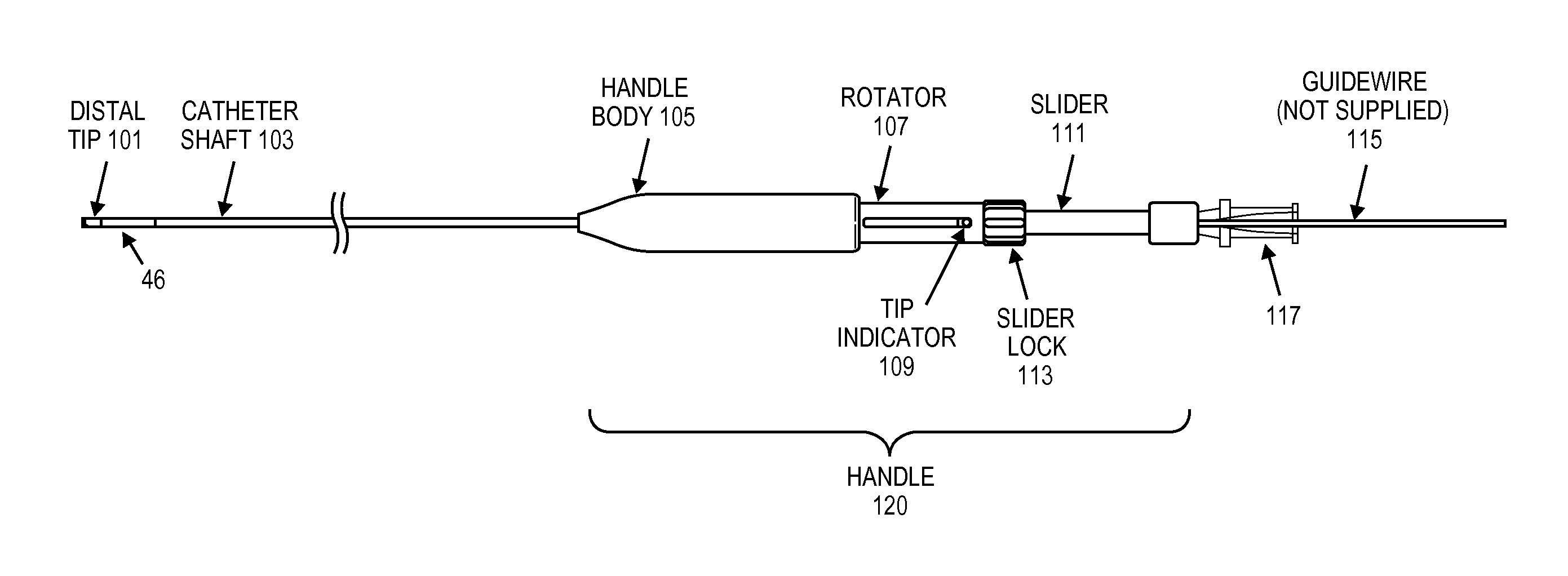
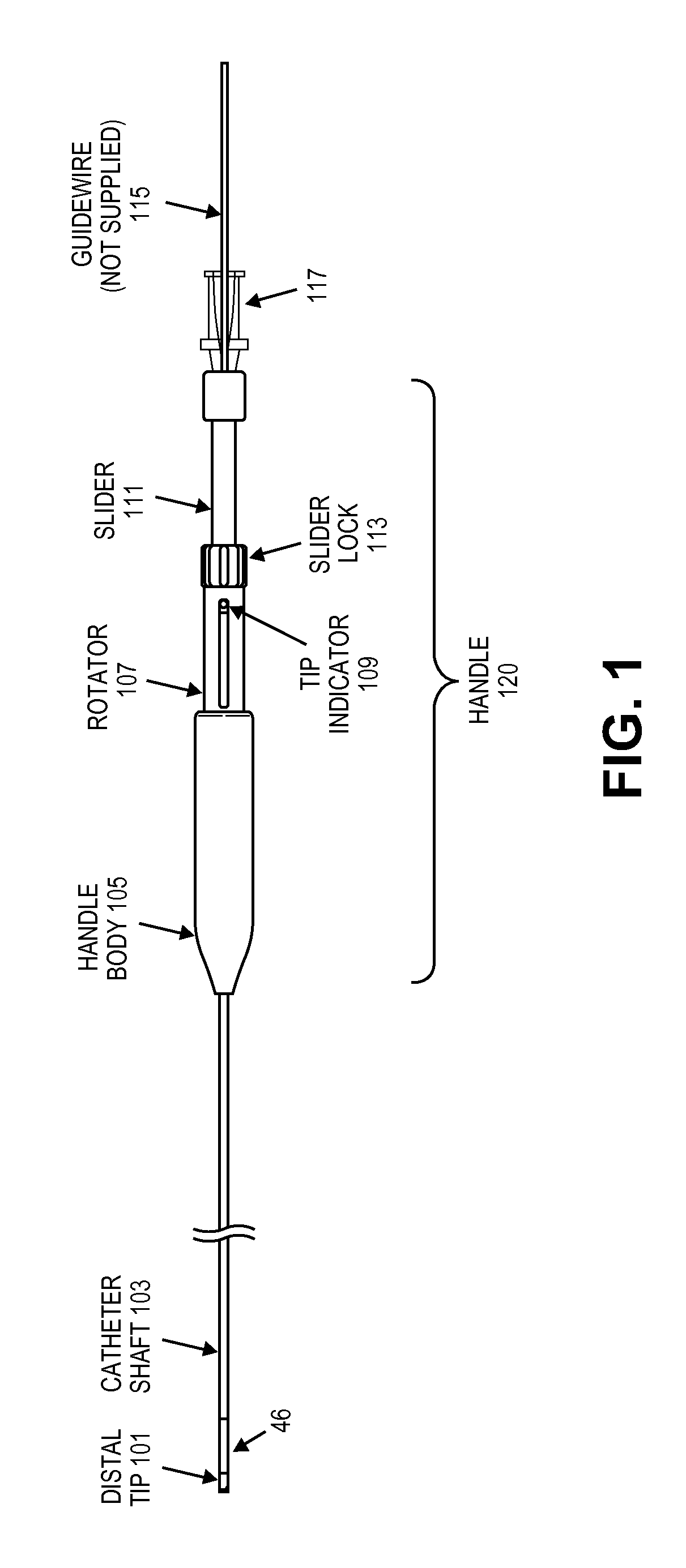
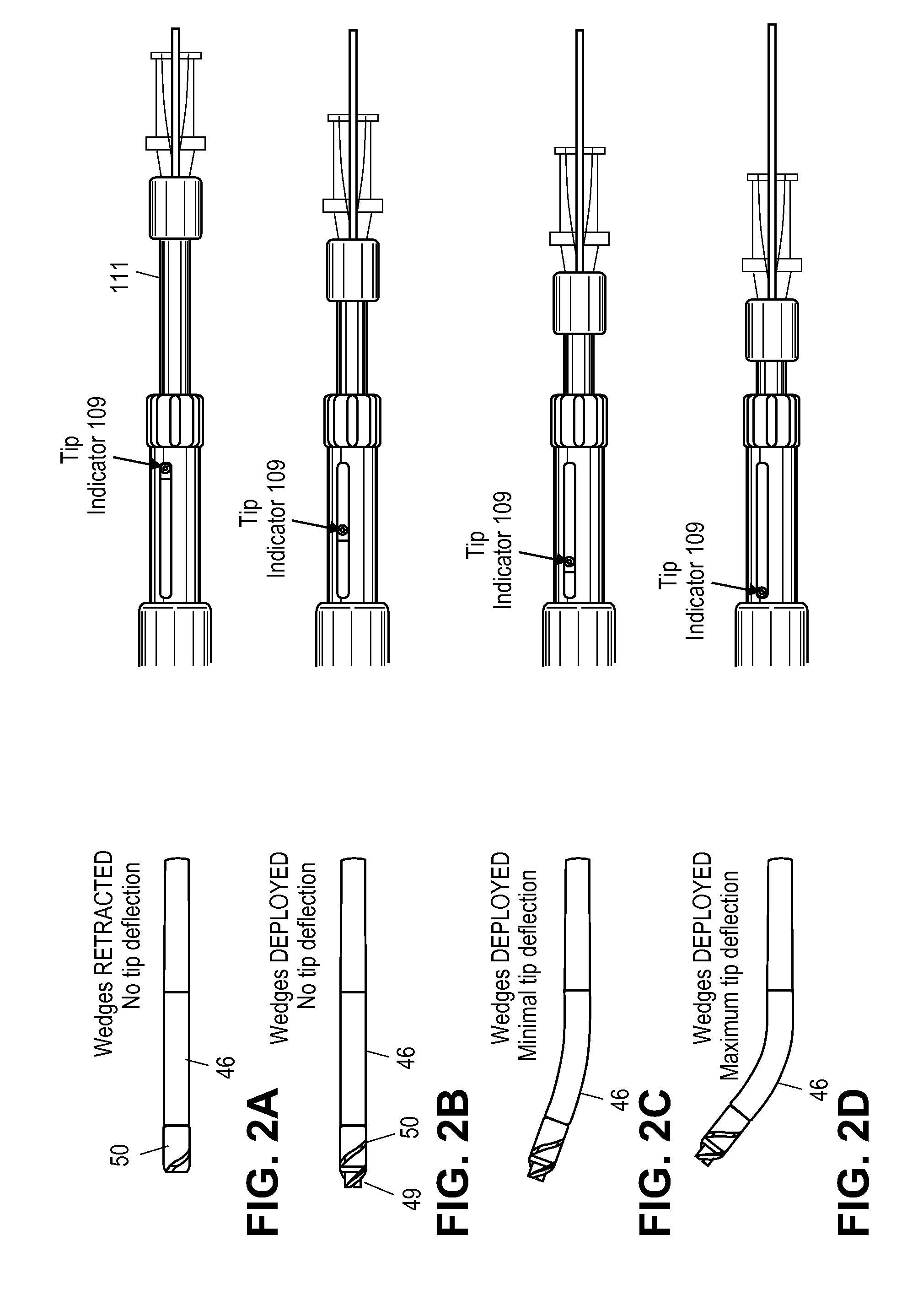
[0091]FIG. 1 illustrates one variation of a guidewire positioning and support catheter having a rotatable distal end with extendable / retractable wedges. This device may be used to position (e.g., providing a channel for) a guidewire or for traversing an occlusion in a vessel, particularly for traversing complete occlusions. This device may be used to support steerable guidewires (and may be used to guide them) in accessing discrete regions of the peripheral vasculature. It may be used to facilitate placement and exchange of guidewires and other interventional devices. It may also be used to deliver saline or contrast.

[0092]One example of such a guidewire support catheter is provided below, although other variations are contemplated. In general, these devices include a rotatable distal tip. The distal tip may be rotated manually (by operation of a control on the proximal handle). In some variations both counterclockwise and clockwise rotation is possible. The devices may include one ...


PUM


Abstract

Described herein are guidewire positioning and support devices, method for using them, method of treating a subject using them, and systems including such guidewire positioning and support devices. These devices typically include a rotatable distal tip region that may include one or more wedges. The wedges may be extendable from the rotatable distal tip. The distal end of the device may be steerable, and may be steered while still rotating the distal end of the device. The wedges (which may include sharp forward-cutting blades and blunt lateral portions) can be extended from the distal housing and locked in any position (extended, partially extended or retracted) and rotated clockwise and/or counterclockwise while locked in a retracted, extended or partially extended position. The distal region of the device may also be controllable steered from the proximal end of the device. Systems including these guidewire support catheters are also described, as are method of using them, including methods of treating chronic total occlusions.

Description

CROSS REFERENCE TO RELATED APPLICATIONS[0001]This patent application claims priority to U.S. Provisional Patent Applications: 61 / 173,542 (filed Apr. 28, 2009), titled “Guidewire Support Catheter;” and 61 / 233,093 (filed Aug. 11, 2009), also titled “Guidewire Support Catheter.” The disclosures of these applications are incorporated herein by reference in their entirety.[0002]This application may be related to U.S. patent application Ser. No. 12 / 108,433, titled “Catheter System and Method for Boring through Blocked Vascular Passages,” filed Apr. 23, 2008, and U.S. patent application Ser. No. 12 / 272,697, titled “Dual-tip Catheter System for Boring through Blocked Vascular Passages,” and filed Nov. 17, 2008. Both of these applications are herein incorporated by reference in their entirety.INCORPORATION BY REFERENCE[0003]All publications and patent applications mentioned in this specification are herein incorporated by reference in their entirety to the same extent as if each individual p...

Claims


Application Information

Patent Timeline
Patent Type & Authority Applications(United States)
IPC IPC(8): A61B17/22A61M25/09
CPCA61B17/320758A61B2017/003A61B2017/00309A61B2017/22038A61B2017/320775A61B5/066A61M25/0138A61M25/0147A61M25/0155A61M25/0172A61M25/01
Inventor PATEL, HIMANSHU N.SIMPSON, JOHN B.
Owner AVINGER
Why Eureka
Try Eureka