Electromagnetic switch for auxiliary-rotation starter

a technology of auxiliary rotation starter and electric switch, which is applied in the direction of engine starter, machine/engine, relay, etc., can solve the problems of deteriorating resistance performance and assembling productivity, and achieves high engagement durability, high productivity, and superior engagement performance.

Active Publication Date: 2012-08-21
MITSUBISHI ELECTRIC CORP
View PDF8 Cites 20 Cited by
  • Summary
  • Abstract
  • Description
  • Claims
  • Application Information

AI Technical Summary

Benefits of technology

[0024]According to the present invention, part of magnetic flux for producing magnetic attractive force that makes the plunger move toward the core flows from the magnetic bypass core to the core via the air gap 13; therefore, even in the case of a conventional ampere-turn electromagnetic switch in which no opposite winding is provided, magnetic attractive force exerted on the plunger and pressing force of the pinion gear against the ring gear are reduced. As a result, there can be obtained an auxiliary-rotation starter that is superior in the engagement between the pinion gear and the ring gear and that has a high engagement durability and a high productivity.

Problems solved by technology

There has been a problem that, in the case where the wire diameter of the coil is decreased, the volume of the conductor is reduced and hence the heat resistance performance is deteriorated because the auxiliary rotation current does not change, and in the case where the wire diameter is increased, the volume of the conductor is enlarged and hence the winding space is expanded, whereby the assembling productivity is deteriorated.

Method used


Image

  • Electromagnetic switch for auxiliary-rotation starter
  • Electromagnetic switch for auxiliary-rotation starter
  • Electromagnetic switch for auxiliary-rotation starter

Examples


embodiment 1

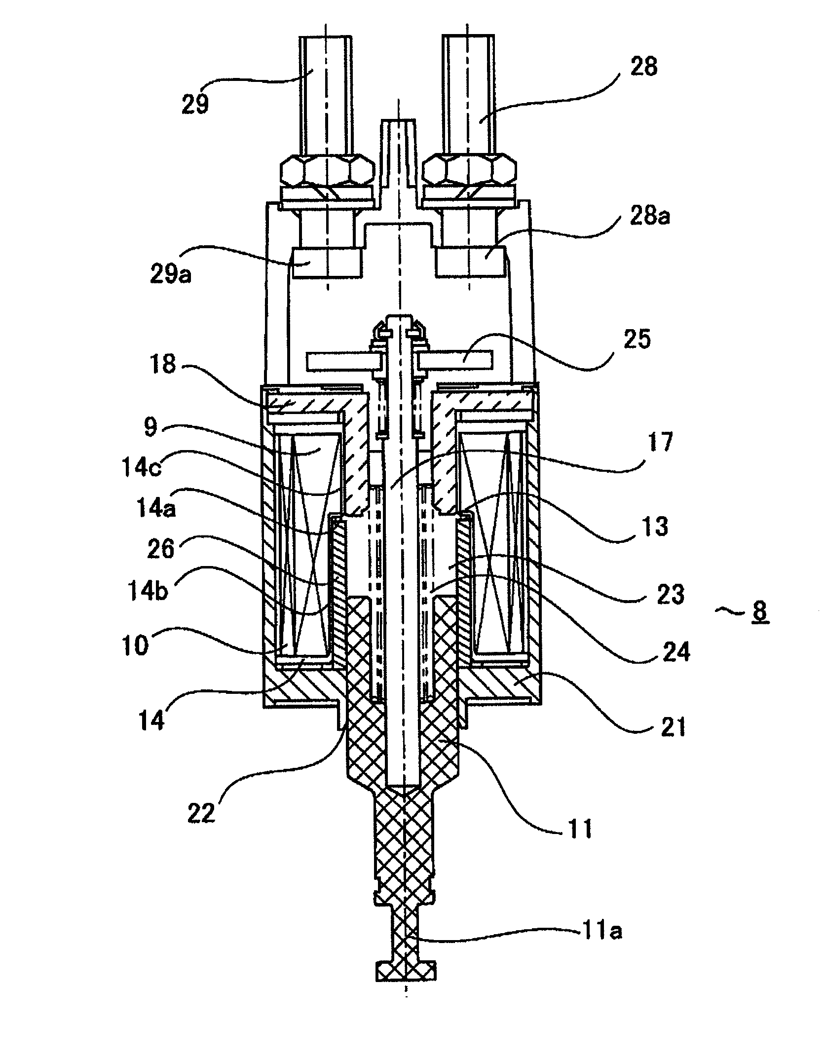
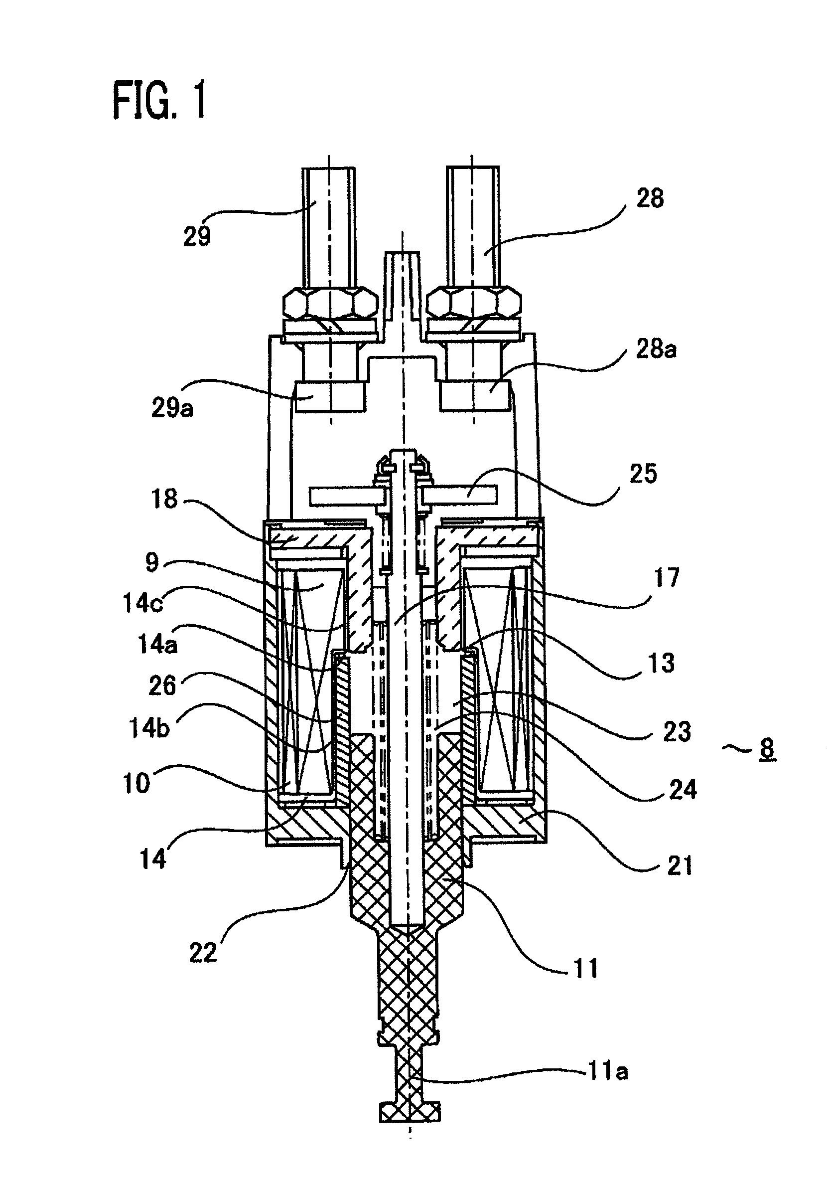
[0030]FIG. 1 is a structural view illustrating the electromagnetic switch for an auxiliary-rotation starter according to Embodiment 1 of the present invention.

[0031]An electromagnetic switch 8 in FIG. 1 is configured with a case 21 that serves as the outer frame of the electromagnetic switch 8 and forms a magnetic circuit, a core 18 fixed on one end of the case 21, a plunger 11 that faces the core 18 by the intermediary of an air gap 23 and protrusively moves from the other end of the case 21, and a bobbin 14 that is disposed in the case 21 in such a way as to enclose part of the core 18 and the plunger 11 and around which an attraction coil 9 and a holding coil 10 are wound.

[0032]An electromagnetic switch for an auxiliary-rotation starter according to the present invention is characterized in that a magnetic bypass core 26 for bypassing part of magnetic flux that is emitted from the plunger 11 and heads for the core 18 is disposed in a place that is inside part of the bobbin 14 and...

embodiment 2

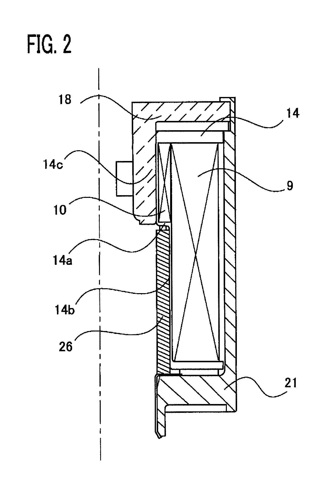
[0040]FIG. 2 is a partial configuration view of a coil according to Embodiment 2 of the present invention. In FIG. 2, the holding coil 10 is wound only around the small-diameter portion 14c in the stepped portion 14a of the bobbin 14; the level difference between the large-diameter portion 14b and the winding circumference of the holding coil 10 is the same as or smaller than half of the coil diameter of the attraction coil 9; the attraction coil 9 is wound in an aligned manner in a space ranging from the outer circumference of the holding coil 10 to the large-diameter portion 14b of the bobbin 14.

[0041]The foregoing configuration makes it possible to utilize the space inside the magnetic switch without loss and to facilitate the winding of the holding coil 10 and the attraction coil 9; therefore, there can be provided a low-cost, high-assembly-efficiency electromagnetic switch, for an auxiliary-rotation starter, that has a high engagement durability such that damage to the ring gea...


PUM

PropertyMeasurementUnit
magnetic fluxaaaaaaaaaa
magnetic attractive forceaaaaaaaaaa
diameteraaaaaaaaaa

Abstract

In an electromagnetic switch for an auxiliary-rotation starter according to the present invention, the magnetic bypass core is disposed at a place that is an air gap portion, in a magnetic circuit, through which the plunger moves due to magnetic attractive force produced by energizing the attraction coil and the holding coil and that is between the outer circumference of the plunger and the inner circumference of the bobbin, in such a way that one end thereof makes contact with one end of the case and the other end thereof faces the end of the core by the intermediary of an air gap.

Description

BACKGROUND OF THE INVENTION[0001]1. Field of the Invention[0002]The present invention relates to an electromagnetic switch for an auxiliary-rotation starter for starting an engine.[0003]2. Description of the Related Art[0004]As a conventional electromagnetic switch for an auxiliary-rotation starter, there has been known an electromagnetic switch (refer to Japanese Patent Application Laid-Open No. 2005-163737) in which, as coil windings, there are utilized two kinds of coils, i.e., an attraction coil that produces magnetic attractive force to be exerted on a plunger coupled with a pinion gear by the intermediary of a lever and a holding coil that produces magnetic holding force for holding the plunger after it is attracted, and when the engine is started by the starter, auxiliary torque for making the starter motor slowly rotate is produced until the contact of the electromagnetic switch is closed, so that, at the same time when pushed out, the pinion gear is smoothly engaged with th...

Claims


Application Information

Patent Timeline
Patent Type & Authority Patents(United States)
IPC IPC(8): H01F7/08
CPCF02N15/067H01H50/36H01H51/065H01H50/42
Inventor KANEDA, NAOHITOKIM, TAEHYUNKAMEI, KOICHIROMORIYAMA, NORIAKITSUKIMA, MITSURU
Owner MITSUBISHI ELECTRIC CORP
Why Eureka
Try Eureka