Secondary conveyor belt cleaner and mounting system therefor

a belt cleaner and conveyor belt technology, applied in the direction of cleaning, conveyor parts, transportation and packaging, etc., can solve the problems of one blade connector frame rubber holders being more prone to cracking, affecting the cleaning effect of conveyor belts, and prone to folding so as to improve the engagement, the effect of improving the positioning of the main blade frame and avoiding the tendency to fold over too often and too easily

Inactive Publication Date: 2009-05-28
METZNER WILLIAM
View PDF17 Cites 20 Cited by
  • Summary
  • Abstract
  • Description
  • Claims
  • Application Information

AI Technical Summary

Benefits of technology

[0009]Preferably, both C-clamps are open-ended but still more box-shaped than curvilinear. With at least three, substantially straight sides, the C-clamps can be pushed into place from the sides of the slotted arms to which they will be bolted. Opposite the “open” end of such C-clamps, there is an outwardly projecting lip or ledge. The lip / ledge to the first and second C-clamps are meant to align when duly installed over their respective slotted arms. Once aligned, the outer lip / ledges of the first and second C-clamps can be interconnected by still other, finely adjustable means. In one particular embodiment, one of the two C-clamp lip / ledges has a threaded aperture through which a bolt passes before contacting the non-apertured lip / ledge of the other partnered C-clamp lip / ledge. In this manner, by rotating the threaded bolt, in one direction or the other, the spacing between C-clamps of this secondary cleaner mount can be finely adjusted affecting a better positioning of the main blade frame against the conveyor belt, from either or both sides.
[0010]In another embodiment, the slotted arms and C-clamp members are replaced by a pair of telescoping structural tube bracket assemblies that each are slotted through two opposing side for interaction with a bolt that holds outer tube members to an inner tube member and allows for adjustment of frame positioning insofar as the frame is mounted on the lower, outer tube member. In addition, the upper and lower outer tube members of the telescoping structuring tube bracket assembly can be adjusted in respect to each other by a bolt or screw adjustment system that interacts with both outer tube members. The main blade frame is attached to the lower external tube and can be adjusted as the position of the two outer tube members is adjusted.
[0011]In addition, for less rotational possibilities within this invention or a typical clamped and tensioned secondary cleaner mount, preferred embodiments of this invention include a rectangular, more preferably square-shaped, cleaning blade frame. For better engagement with the conveyor belt being cleaned, this rectangular blade frame has two or more mounting crossbar connectors extending upwardly and outwardly from one side. Such mounting is significantly improved in terms of blade contact and sweep when compared with the circular blade frames of the prior art from which only one crossbar connector projects upwardly and outwardly. A main advantage of mounting rubber blades mount between two crossbar connectors atop the blade frame, as opposed to bolting through only one upwardly extended crossbar, is that prior art single connector arrangements apply less forces against the conveyor for fine adjustment at the point of tangency, i.e., where the belt leaves the head (or front) pulley. Preferably, the blades that perform secondary cleaning should push into the conveyor belt about ⅛″ inch or more. Once the conveyor begins running, the cleaning blades will flex back and forth via their rubber mounts. On a single crossbar connector, these blades may fold over too often and too easily. And with excessive “fold over” and “over movement”, the rubber holders of a one blade connector frame are more prone to crack at their weakest points rendering them useless for continuous conveyor belt cleaning. And while these rubber blade holders can be replaced, their replacement is costly in terms of materials and productivity. With the preferred, two crossbar configurations of this invention, rubber blade mount breakage is less likely to happen.

Problems solved by technology

On a single crossbar connector, these blades may fold over too often and too easily.
And with excessive “fold over” and “over movement”, the rubber holders of a one blade connector frame are more prone to crack at their weakest points rendering them useless for continuous conveyor belt cleaning.
And while these rubber blade holders can be replaced, their replacement is costly in terms of materials and productivity.

Method used


Image

  • Secondary conveyor belt cleaner and mounting system therefor
  • Secondary conveyor belt cleaner and mounting system therefor
  • Secondary conveyor belt cleaner and mounting system therefor

Examples


Embodiment Construction

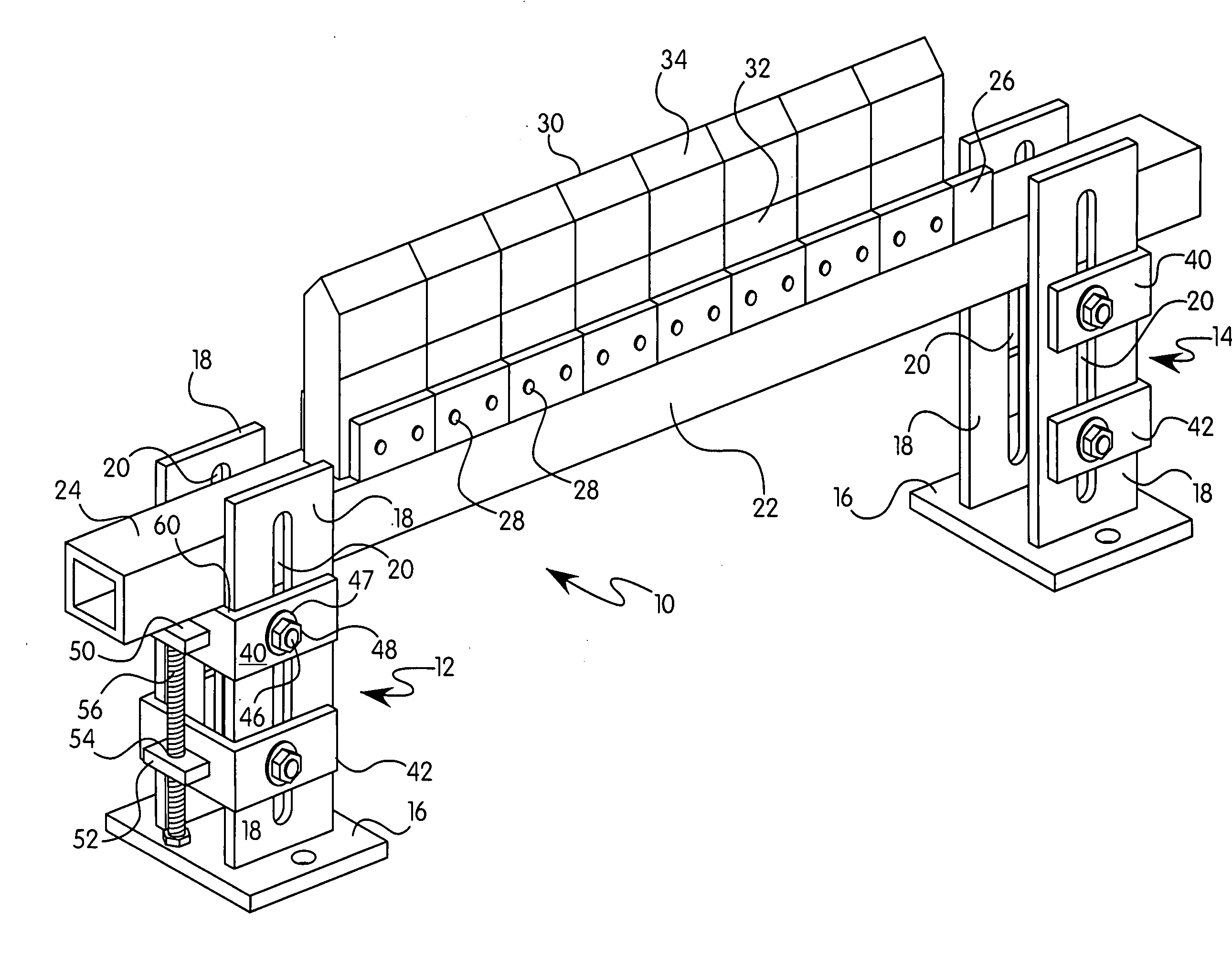
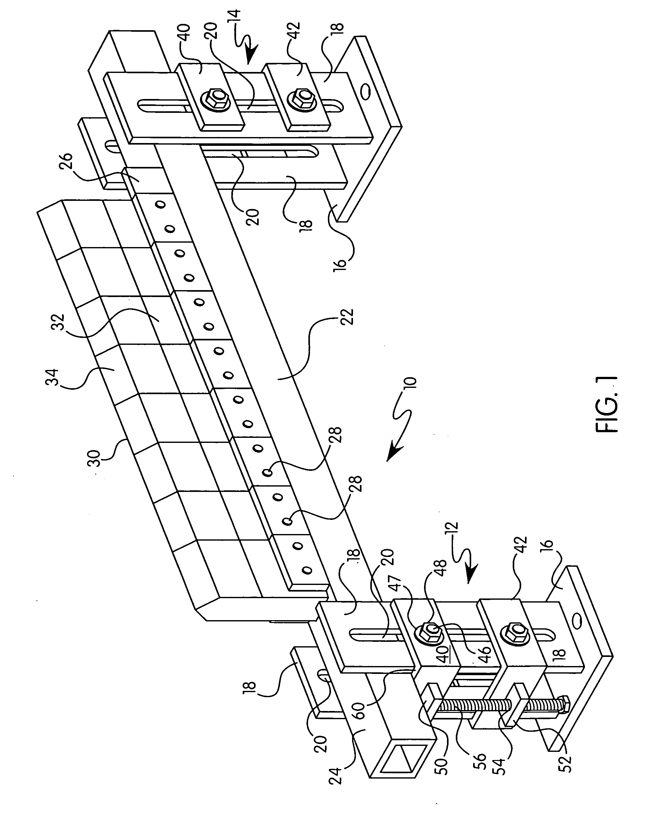
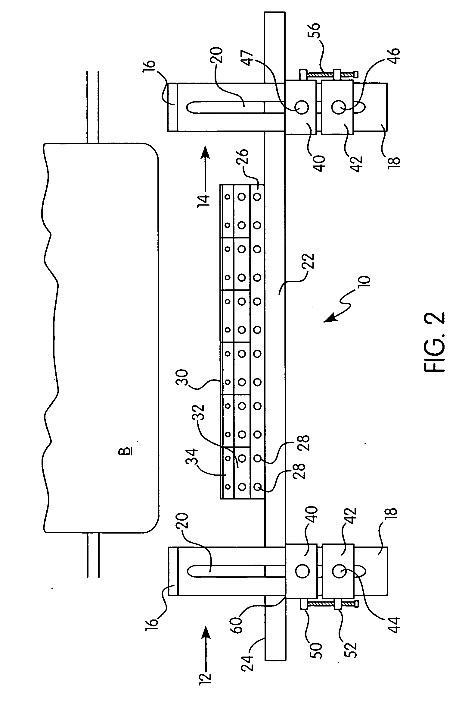
[0027]In FIGS. 1 through 12, a secondary cleaning system 10 for a conveyor belt in accordance with one preferred embodiment of this invention is illustrated. The cleaning system, generally 10, includes a pair of side brackets 12 and 14 for positioning on either side of a conveyor belt, shown for relative positioning as component B in FIG. 2. Each side bracket 12 and 14 has a mounting base 16 from which a pair of slotted arms 18 outwardly extends. The slots 20 in each slotted arm pair 18 align for receiving one or more bolts to connect other cleaner mount components to the side brackets 12 and 14.

[0028]The slotted arms 18 of preferred embodiments are spaced apart a set distance that should approximate the width of a cleaning blade, frame bar 22. As best seen in FIGS. 9 and 10, frame bar 22 is rectangularly shaped, preferably square in cross section. One embodiment of frame bar 22 is made from a hollow metal extrusion. With a non-circular cross-section, frame bar 22 will not rotate be...


PUM


Abstract

A secondary system for cleaning a belt running between conveyor pulleys. The secondary system is comprised of a frame bar on which cleaning blades are mounted, two bracket assemblies to which the frame bar is adjustably mounted and an adjustment system mounted on the external sides of the bracket assemblies. In one embodiment, the bracket assemblies each include a pair of slotted arms over which two or more clamps are joined together. In another embodiment, each bracket assembly is comprised of an inner tube member that telescopes into two outer tube members, i.e., and an upper member that can be adjustably clamped to the inner tube and a lower tube member to which the frame bar is mounted and that is attached to said upper member by the adjustment system. The frame bar and bracket assemblies have rectangular cross-section so that, when mounted to each other, rotational movement of frame bar about its longitudinal axis is prohibited. This rotational prohibition is independent from the adjustment system for the frame bar positioning.

Description

CROSS-REFERENCE TO RELATED APPLICATION[0001]This application claims priority under 35 U.S.C. §119(e) to Provisional Application Ser. No. 60 / 998,182, filed Oct. 9, 2007, incorporated by reference in its entirety.FIELD OF THE INVENTION[0002]The present invention relates to belt cleaning systems for conveyor belts and, particularly, to secondary belt cleaning systems. More particularly, this invention relates to an improved mounting system for a secondary belt cleaner that does not require a twister or “tensioner” for holding the cleaner blade or blades firmly against a moving conveyor belt. The mounting system of this invention places fine tuning adjusters on the outside or outer edges of a belt cleaner, much more accessible than the interior adjustment means of many prior art cleaners.BACKGROUND OF THE INVENTION[0003]It is known to use scraping style cleaners for a conveyor belt to remove debris and other materials from the belt. Such belts function in different capacities depending ...

Claims


Application Information

Patent Timeline
Patent Type & Authority Applications(United States)
IPC IPC(8): B65G45/12
CPCB65G45/12
Inventor METZNER, WILLIAM
Owner METZNER WILLIAM
Why Eureka
Try Eureka