System and method for moving an object employing piezo actuators

a technology of piezo actuators and actuators, which is applied in the field of system and method of moving an object using piezo actuators, can solve the problems of limited piezo actuator range, large range of linear movement of objects, and limited lengthening or shearing of piezo materials

Inactive Publication Date: 2005-12-20
ASML NETHERLANDS BV
View PDF9 Cites 23 Cited by
  • Summary
  • Abstract
  • Description
  • Claims
  • Application Information

AI Technical Summary

Benefits of technology

[0013]In one embodiment, the piezo actuator system moves an object primarily using the linear mode of a piezo actuator. The piezo actuator engages the object and shears. The object may thus be displaced over a maximum distance corresponding to the maximum shear distance of the piezo actuator. The piezo actuator does not contract and expand for moving the object within the shearing range of the piezo actuator. Without contracting and expanding, i.e. lengthening, for moving an object over a distance within the shearing range of the piezo actuators, the lifetime of the piezo actuators is substantially increased.
[0016]It is to be noted that the present invention may be employed with any piezo actuator system, wherein the piezo actuators may exert a force on an object in a first direction for moving the object in the first direction and in a second direction, preferably substantially perpendicular to the first direction, for engaging said object. For example, in one embodiment, a piezo actuator is formed by two piezo sub-actuators positioned opposite to each other, and the object is engaged through clamping the object between the two piezo sub-actuators. The sub-actuators engage the object together and move it in the desired direction. Such an embodiment of the piezo actuators ensures a good engagement of the actuator with the object.
[0028]The shuffle sequence as described above is performed as quickly as possible since the object does not substantially move during the shuffle sequence resulting in a dead time. In a further embodiment of the present invention, the system is further adapted to perform a slow shuffle sequence wherein the shuffle sequence is performed relatively slowly, and during which the linear shear sequence may be performed simultaneously, thus preventing any dead time during actuation.
[0031]When the slow shuffle sequence is started, a shuffle start control signal is provided to the integrator. In response to this shuffle start control signal, the integrator resets its output to zero. During the slow shuffle sequence, the second control signal is the sum of the controller force signal and a shuffle control signal. At the start of the slow shuffle sequence, the value of the second control signal is copied to the second shuffle control signal. Then, the integrator is reset as mentioned above, setting its output to zero. Thus, the second control signal being a sum of the second shuffle control signal and the integrator output is kept substantially the same when starting the slow shuffle sequence, providing a smooth transition to the slow shuffle sequence.
[0032]During the slow shuffle sequence, the second shuffle control signal is gradually decreased to zero and the integrator output may increase. When the second shuffle control signal is decreased to zero, the slow shuffle sequence has ended and the integrator output forms the second control signal, providing a smooth transition from the slow shuffle sequence to the linear shear sequence.

Problems solved by technology

The lengthening or shearing of the piezo material is limited.
It is a disadvantage of the stepping mode that even for small moves, the piezo actuators need to contract and expand.
However, as mentioned above, the range for moving an object in a linear mode is very small.

Method used


Image

  • System and method for moving an object employing piezo actuators
  • System and method for moving an object employing piezo actuators
  • System and method for moving an object employing piezo actuators

Examples


second embodiment

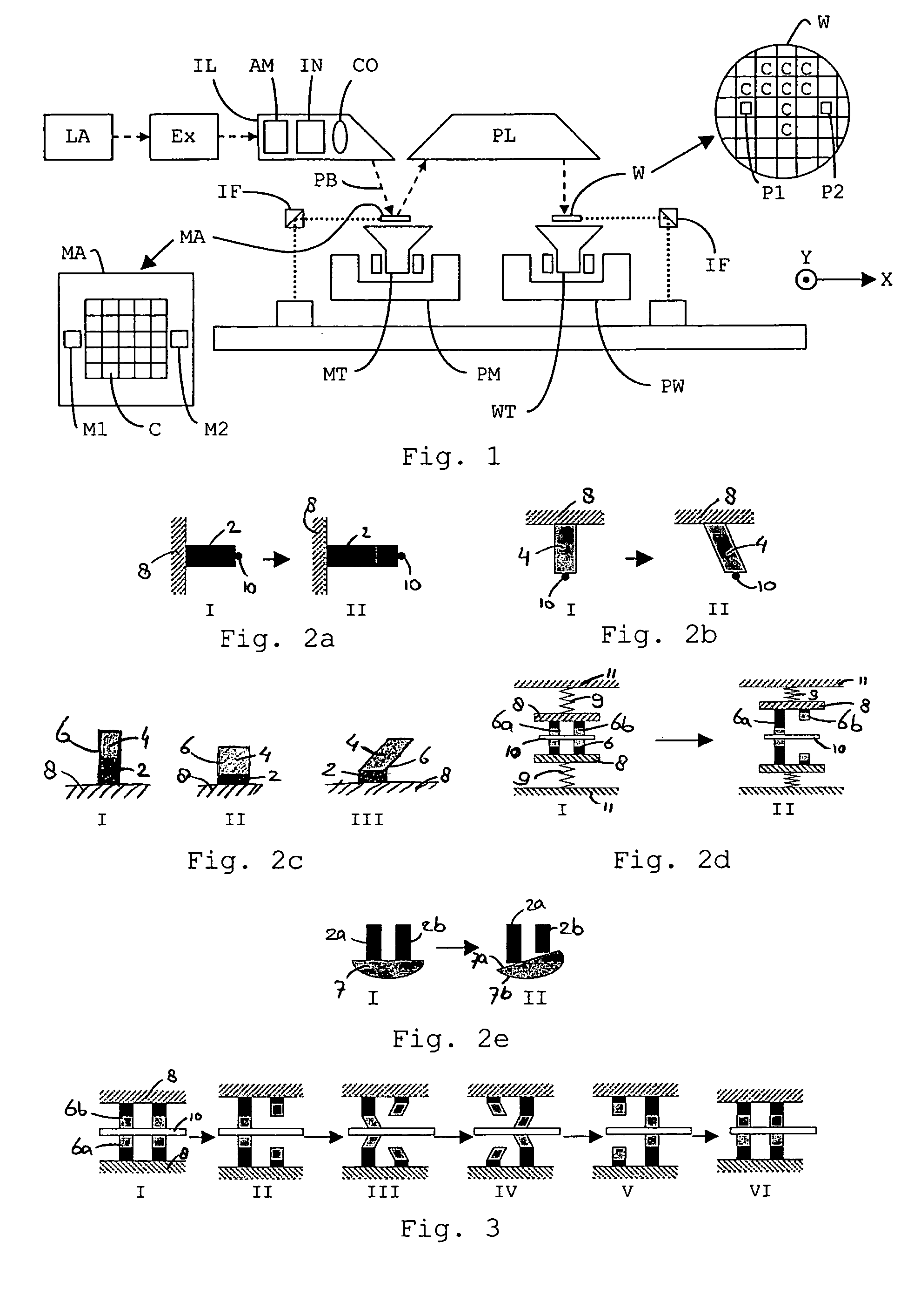
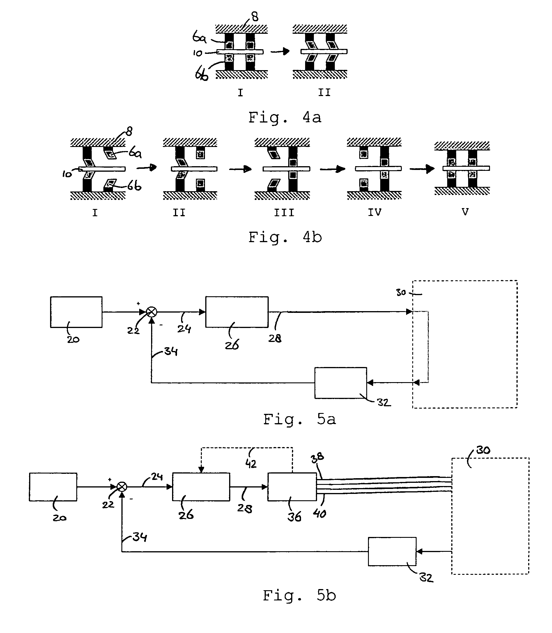
[0074]FIG. 2d (I) illustrates an embodiment of an actuator comprising four piezo actuators 6 as shown in FIG. 2c. An object 10 is engaged by said four piezo actuators 6. The piezo actuators 6 are positioned on a base material 8. The base material 8 is attached to a reference system 11 using springs 9. When no control signal is supplied to the piezo actuators 6, i.e. the piezo actuators 6 are relaxed (I), the object 10 is engaged by the piezo actuators 6 as a result of the spring load. To release the engagement with the object 10, a first piezo actuator 6a may expand while a second piezo actuator 6b contracts, as illustrated in FIG. 2d (II). Thus, the first piezo actuator 6a grips the object 10, while the second piezo actuator 6b releases its engagement.

third embodiment

[0075]FIG. 2e (I) shows another embodiment of a piezo actuator system for moving an object 10. The piezo actuator system comprises two lengthening piezo actuators 2a and 2b, and a semi-circular friction element 7. A flat surface 7a of the friction element 7 is positioned against the piezo actuators 2a and 2b. A convex surface 7b of the friction element 7 may engage an object. As shown in FIG. 2e (II), by expanding one piezo actuator 2a and possibly contracting another piezo actuator 2b, the friction element 7 rotates over a predetermined angle. When the friction element 7 is positioned with its convex surface 7b against an object 10, the object 10 will move due to friction between the friction element 7 and the object 10. Contracting both piezo actuators 2a and 2b releases the engagement of the friction element 7 with the object 10.

[0076]It is noted that in the embodiment shown in FIG. 2e, the piezo actuator system lengthens when both piezo actuators 2a and 2b contract or expand. Th...

fourth embodiment

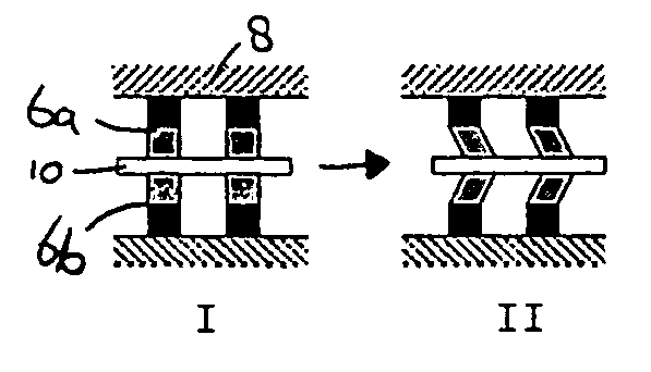
[0077]FIG. 3 illustrates a prior art system comprising a number of piezo actuators 6, in this case two, for moving an object 10 over a larger distance than the maximum lengthening or shearing of a single piezo actuator 6. In the system shown in FIG. 3, the piezo actuators 6 comprise two sub-actuators 6a, 6b which are positioned opposite to each other. The actuators 6 grip the object 10 by clamping the object 10 between the two sub-actuators 6a and 6b (I).

[0078]In a first step (II) to move the object 10, one of the actuators 6 releases its engagement with the object 10 by contracting away from the object 10. Then, in a second step (III), the actuator 6 still engaging the object 10 shears in a desired movement direction, for example right, while the other actuator 6, still contracted, shears opposite to the movement direction, e.g. left. The actuator 6 engaging the object 10 and shearing in the direction of movement takes the object 10 along, and thus the object 10 moves in the desire...


PUM

PropertyMeasurementUnit
voltageaaaaaaaaaa
chargeaaaaaaaaaa
lengthaaaaaaaaaa

Abstract

A piezo actuator system, is presented herein. A piezo actuator system comprises a number of piezo actuators which may lengthen and shear. Using the lengthening and shearing, the piezo actuator system grips and moves an object in response to a first and a second control signal, respectively. The possible displacement of the object is limited by the maximum shear of the piezo actuators. To increase the possible displacement, the piezo actuators may be controlled to perform a linear shear sequence or a shuffle sequence. During the linear shear sequence, the object is moved; during the shuffle sequence the object is substantially stationary, while the piezo actuators are repositioned with respect to the object, after which the object may be moved further using the linear shear sequence.A piezo actuator system may be adapted to perform a slow shuffle sequence, being a relatively slowly performed shuffle sequence, during which the linear shear sequence may be performed simultaneously, preventing any dead time during movement.

Description

BACKGROUND OF THE INVENTION[0001]1. Field of the Invention[0002]The present invention relates to a system and method for moving an object using piezo actuators and, more particularly, to a system for moving an object associated with lithographic apparatus.[0003]2. Description of the Related Art[0004]A lithographic apparatus is a machine that applies a desired pattern onto a target portion of a substrate. Lithographic apparatus can be used, for example, in the manufacture of integrated circuits (ICs). In that circumstance, a patterning device, such as a mask, may be used to generate a circuit pattern corresponding to an individual layer of the IC, and this pattern can be imaged onto a target portion (e.g. comprising part of, one or several dies) on a substrate (e.g. a silicon wafer) that has a layer of radiation-sensitive material (resist).[0005]In general, a single substrate will contain a network of adjacent target portions that are successively exposed. Known lithographic apparatu...

Claims


Application Information

Patent Timeline
Patent Type & Authority Patents(United States)
IPC IPC(8): B81B7/02B81B3/00G03F7/20H01L21/027H01L41/09H02N2/00
CPCG03F7/70758H02N2/021G03F7/70825G03F7/70716
Inventor HENDRIKS, STEFAN GERTRUD MARIEMATTAAR, THOMAS AUGUSTUSLEENHEERS, GERARDUS JACOBUS CORNELIS CATHARINA MARIA
Owner ASML NETHERLANDS BV
Why Eureka
Try Eureka