Central conductor of coaxial cable connector

a technology of coaxial cable connector and central conductor, which is applied in the direction of coupling device connection, coupling contact member, coupling device details, etc., can solve the problems of unstable signal transmission, resilient fatigue, and improper clamping of the internal conductor of the coaxial cable, so as to improve the clamping force and increase the contact area , excellent engagement

Active Publication Date: 2012-10-30
EZCONN
View PDF8 Cites 23 Cited by
  • Summary
  • Abstract
  • Description
  • Claims
  • Application Information

AI Technical Summary

Benefits of technology

[0008]As such, multiple pairs of spring plates are provided to enhance clamping force and prevent an internal conductor of a coaxial cable from being easily pulled off and increase contact area to provide excellent engagement between conductors, and multiple slits are provided to improve resiliency limit, and the barrel is integrally formed as a single piece to thereby reduce the cost.

Problems solved by technology

However, such a pair of spring plates is not mechanically strong enough to securely clamp the internal conductor of the coaxial cable, whereby it often occurs that the transmission of signal is unstable or even interrupted.
If poorly structured, the central conductor of the conventional coaxial cable connector, when put into mating engagement with an internal conductor of a coaxial cable, is susceptible to over-expansion of the connection structure of the central conductor, which often leads to resilient fatigue and improper clamping of the internal conductor of the coaxial cable by the connection structure.

Method used


Image

  • Central conductor of coaxial cable connector
  • Central conductor of coaxial cable connector
  • Central conductor of coaxial cable connector

Examples


first embodiment

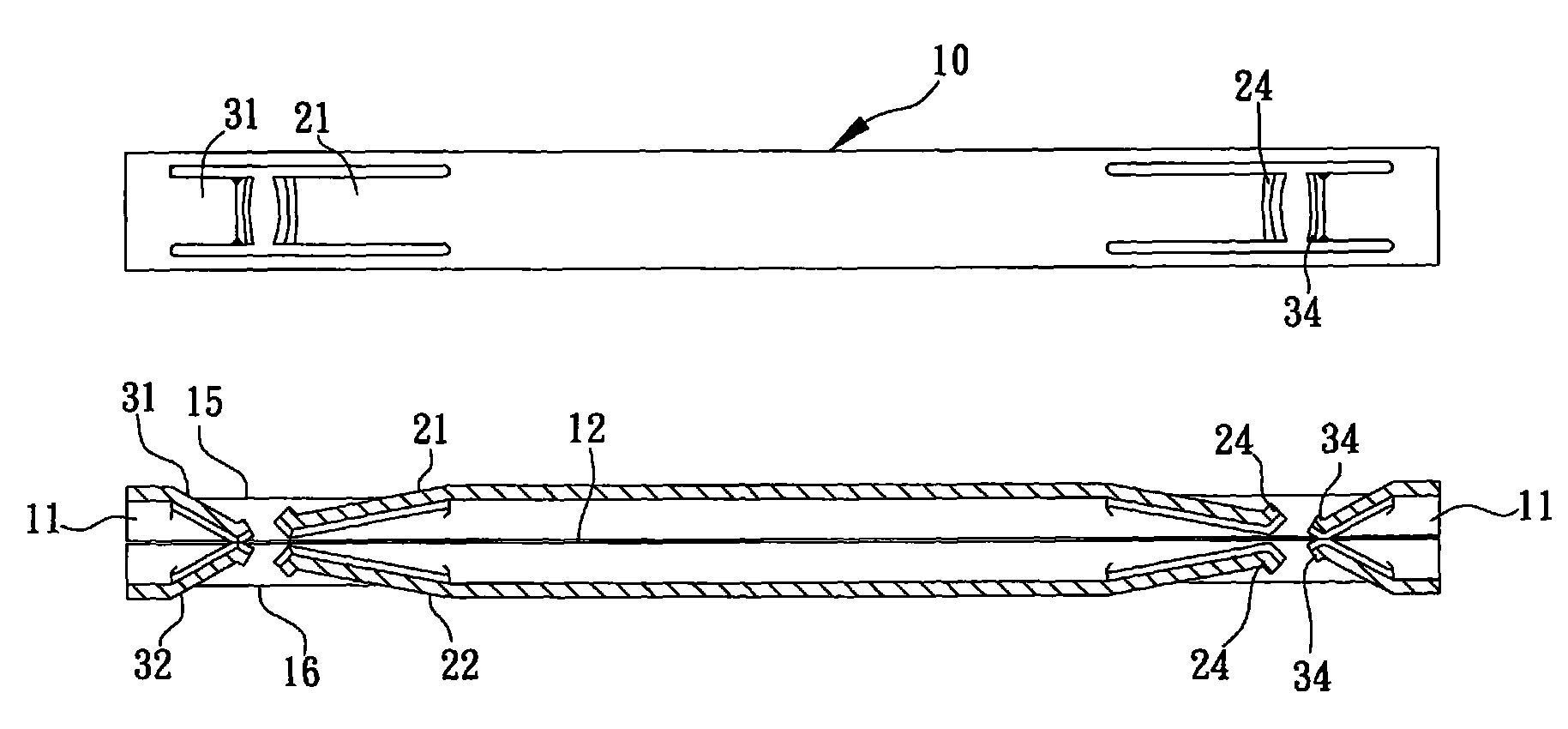
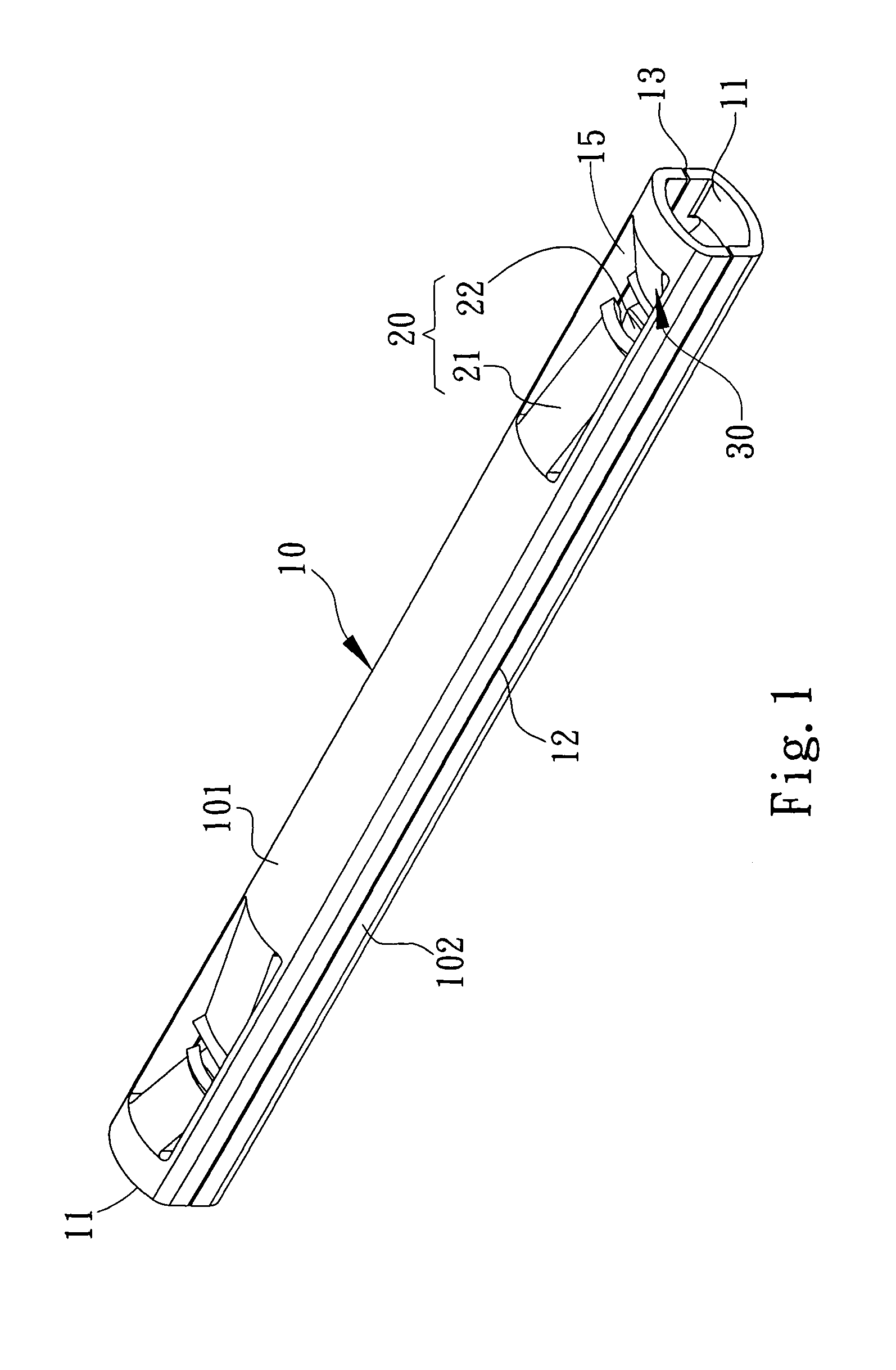
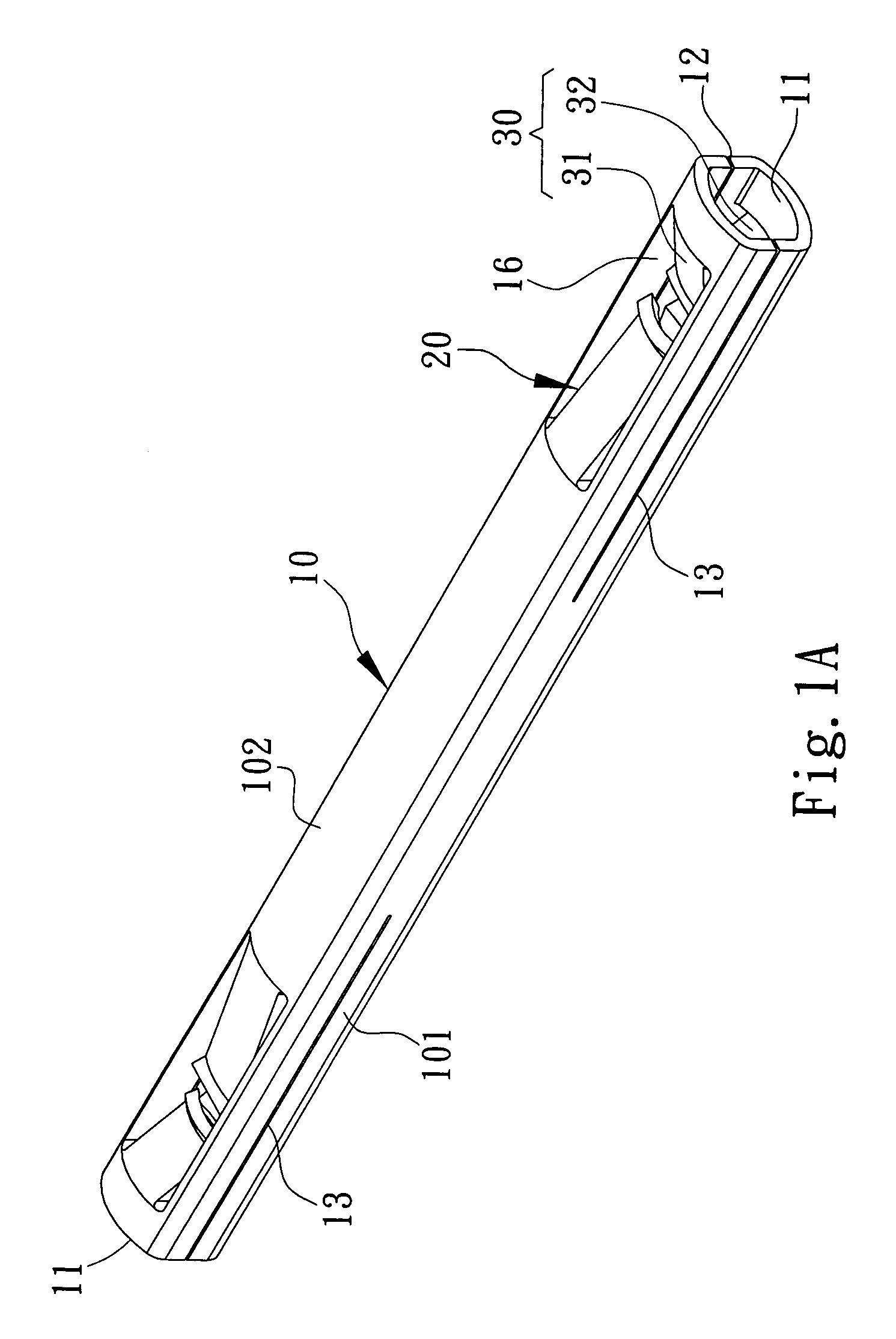
[0022]With reference to the drawings and in particular to FIGS. 1-4, an improved structure of central conductor of coaxial cable connector is shown, comprising a hollow barrel 10, at least one first spring plate group 20, and at least one second spring plate group 30.

[0023]The barrel 10 has a front end and a rear end in an axial direction, which respectively form connection bores 11. The barrel 10 has opposite, left and right side surfaces, which respectively form a first slit 12 and a second slit 13. The barrel 10 has top and bottom walls 101, 102, which form at least one top wall opening 15 and at least one bottom wall opening 16 corresponding to each other. The first slit 12 is a continuous slit that extends from the connection bore 11 of the front end of the barrel 10 to the connection bore 11 of the rear end of the barrel 10, while the second slit 13 is an interrupted slit of two segments respectively extending from the connection bore 11 of the front end of the barrel 10 and t...

second embodiment

[0030]With reference to FIG. 6, a second embodiment of a central conductor of coaxial cable connector according to the present invention is shown. The second embodiment is different from the above-described first embodiment in that the spring plates 21, 22 of the first spring plate group 20 and the spring plates 31, 32 of the second spring plate group 30 are arranged in directions that are opposite to those of the first embodiment and thus present an arrangement of two pointing-away V-shapes. This provides the same advantage as that of the first embodiment.

third embodiment

[0031]Referring to FIGS. 7 and 7A, a third embodiment of central conductor of coaxial cable connector according to the present invention is shown and is different from the first embodiment in that the barrel 10 has one end (front end or rear end) that is reduced, in a stepwise manner, to form a cylindrical tube for connection with connectors of different specifications and thereby improving applicability of the present invention to diverse electronic products. It is apparent that the cylindrical end of the barrel 10 can be extended as desired, as shown in FIG. 7B.


PUM


Abstract

A central conductor of coaxial cable connector includes a barrel, at least one first spring plate group, and at least one second spring plate group. The barrel has two ends forming connection bores, opposite side surfaces respectively forming a first slit and a second slit, and top and bottom walls respectively forming a wall opening and a bottom wall opening. The first spring plate group and the second spring plate group are arranged opposite in direction to each other and each includes spring plates that are arranged to engage each other from upper and lower sides. Each of the spring plates has an end connected to the top or bottom wall of the barrel and an opposite end extending inward of the top wall opening or the bottom wall opening. As such, clamping force is enhanced, contact area is increased, and resiliency limit is improved, so as to provide excellent engagement between conductors.

Description

FIELD OF THE INVENTION[0001]The present invention relates to an improved structure of central conductor of coaxial cable connector, wherein the central conductor is arranged inside a coaxial cable connector for connection with coaxial cables, as well as internal conductors thereof, which are of different specifications.BACKGROUND OF THE INVENTION[0002]To transmit signals in relation with applications of high frequency, video signals, and cable television systems, a coaxial cable connector is provided in the system for connecting at least one coaxial cable in order to accomplish the transmission of signal. With the significant progress in developing different types of electronic products, due to the concerns of frequency stabilization and reduction of transmission loss for signal transmission, coaxial cable connectors that have various specifications and mated coaxial cables have been developed for different types of electronic devices, in order to provide effective isolation against...

Claims


Application Information

Patent Timeline
Patent Type & Authority Patents(United States)
IPC IPC(8): H01R11/22
CPCH01R4/4818H01R24/40H01R4/48185
Inventor CHEN, MING-CHING
Owner EZCONN
Why Eureka
Try Eureka