Artificial valve prosthesis with valve leaflet clamping device

A technology of artificial valve and clamping device, which is applied in the field of medical devices, can solve problems such as postoperative stent falling off, artificial valve prosthesis displacement, and threats to the life safety of patients, so as to reduce the dependence on radial support force and avoid complications. disease effect

Active Publication Date: 2015-01-14
NINGBO JENSCARE BIOTECHNOLOGY CO LTD
View PDF13 Cites 34 Cited by
  • Summary
  • Abstract
  • Description
  • Claims
  • Application Information

AI Technical Summary

Problems solved by technology

The disadvantage of this design is that, since the bracket is cut in one piece, the cutting space of the positioning arch and the holding arch must not overlap each other, and there are at least three problems in the bracket after being shaped like this: one is the shape after shaping. The positioning arches and the retaining arches do not overlap with each other, and when the autogenous valve leaflet is clamped between the positioning arches and the retaining arches, only the line contact of several rods, the autologous Under the action of blood flow, the valve leaflets still vibrate to a large extent in the gap between the rods, which affects the normal movement of the artificial valve prosthesis and reduces the effective opening area; The parts are clamped by line contact, and the insufficient clamping force will easily cause the displacement of the artificial valve prosthesis; the third is that the design sutures the annulus of the artificial valve on the retaining arch, although the positioning arch is cut when the stent is cut. The bottom end of the prosthesis is flat with the annulus of the artificial valve, but the end of the positioning arch is likely to be located above the annulus of the artificial valve after being stretched and shaped. If the positioning arch is used for positioning, the artificial The valve is artificially placed in the lower position of the native valve annulus, becoming "intra-annular" or even "sub-annular", which further reduces the effective opening area
[0010] To sum up, the existing design of aortic valve stents cannot completely solve the problem of positioning and anchoring. Once inaccurate positioning causes coronary artery blockage or postoperative stent fall-off, it will directly threaten the life safety of patients.
However, the existing technologies that use native valves for clamping to improve the anchoring effect also have their own problems.

Method used


Image

  • Artificial valve prosthesis with valve leaflet clamping device
  • Artificial valve prosthesis with valve leaflet clamping device
  • Artificial valve prosthesis with valve leaflet clamping device

Examples


specific Embodiment 1

[0067] The distal end in this embodiment refers to the end away from the apex of the heart, and the proximal end refers to the end close to the apex of the heart.

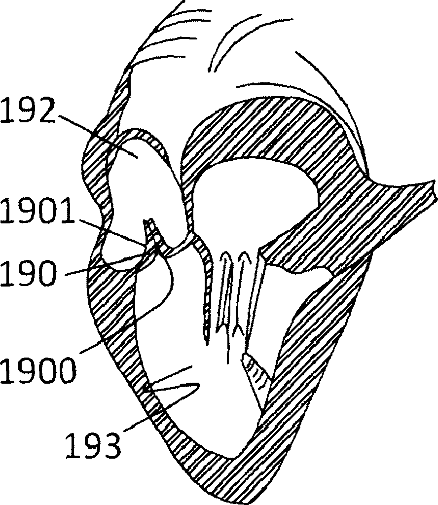
[0068] Such as Figure 1a As shown, when the left ventricle 193 contracts so that the blood pressure of the left ventricle 193 is higher than the blood pressure of the aorta 192, blood rushes from the left ventricle 193 through the aortic valve and enters the aorta 192, and when the left ventricle 193 relaxes, the blood pressure of the left ventricle 193 is lower than When the aorta 192 has blood pressure, the aortic valve closes, and at this moment, the contact of adjacent native valve leaflets 190 forms a closed surface 1900. At this time, the other surface 1901 of the valve leaflet 190 on one side of the aorta 192 is defined as the native valve leaflet. Opposite side of closed face. Such as Figure 1b with Figure 1c As shown, the artificial valve prosthesis 100 with leaflet clamping device of the present inve...

specific Embodiment 2

[0073] The distal end in this embodiment refers to the end away from the apex of the heart, and the proximal end refers to the end close to the apex of the heart.

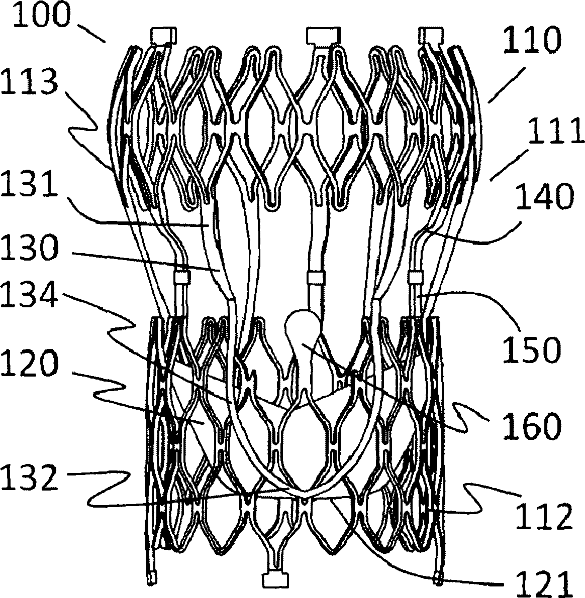
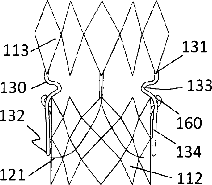
[0074] In another embodiment of the present invention, as Figures 6a-6c As shown, the artificial valve prosthesis 200 with leaflet clamping device includes a stent 210 and an artificial valve 220, the stent 210 includes an auxiliary support clamping section 211 and a valve sewing section 212, and the artificial valve 220 It is fixedly connected to the valve sewing section 212, and the auxiliary support clamping section 211 is composed of a support bracket 213, a valve leaflet clamping device 230 and an upper connecting fixed section 240, and the valve leaflet clamping device 230 is connected with the valve leaflet clamping device 230. The supporting bracket 213 and the upper connecting and fixing section 240 are integrally cut, and the valve sewing section 212 is provided with a lower connecting and fixing section...

specific Embodiment 3

[0091] The distal end in this embodiment refers to the end away from the apex of the heart, and the proximal end refers to the end close to the apex of the heart.

[0092] In another embodiment of the present invention, as Figures 19a-19d As shown, the artificial valve prosthesis 300 with leaflet clamping device includes a stent 310 and an artificial valve (not shown), the stent 310 includes an auxiliary support clamping section 311 and a valve sewing section 312, the An artificial valve (not shown) is fixedly connected to the valve sewing section 312, and the auxiliary support clamping section 311 is composed of a support bracket 313, a leaflet clamping device 330 and an upper connecting fixed section 340, and the valve leaflet The clamping device 330 is cut integrally with the supporting bracket 313 and the upper connecting and fixing section 340 , and a lower connecting and fixing section 350 matching the upper connecting and fixing section 340 is provided on the valve sew...


PUM


Abstract

The invention relates to artificial valve prosthesis with a valve leaflet clamping device. The manual valve prosthesis comprises a bracket and an artificial valve, wherein the bracket comprises an auxiliary support clamping section and a valve sewing section; the artificial valve is fixedly connected to the valve sewing section; the auxiliary support clamping section is composed of a support bracket, a valve leaflet clamping device and an upper connection fixing section; the leaflet clamping device, the support bracket and the upper connection fixing section are integrally cut; a lower connection fixing section matched with the upper connection fixing section is arranged on the valve sewing section; the bracket is embedded and connected with the lower connection fixing section into a whole through the upper connection fixing section; one part of the valve leaflet clamping device is overlapped with the valve sewing section; the overlapped part is tightly attached to the outer surface of the valve sewing section in a natural state; a bump which protrudes outwards along the radial direction is arranged on a skeleton structure of the valve sewing section in the overlapped region; and a bending section which bends towards the axis direction of the bracket along the radial direction of the bracket is arranged on the valve leaflet clamping device or the support bracket or the upper connection fixing section.

Description

Technical field: [0001] The invention belongs to the field of medical devices, and in particular relates to an artificial valve prosthesis with a leaflet clamping device. Background technique: [0002] Aortic stenosis is mainly caused by sequelae of rheumatic fever, congenital aortic valve structural abnormalities, or senile aortic valve calcification. Patients are asymptomatic during the compensation period, but most patients with severe aortic stenosis have symptoms of fatigue, dyspnea (exertional or paroxysmal), angina pectoris, dizziness or syncope, and even sudden death. [0003] Aortic valve regurgitation means that the aortic valve opens when the ventricle contracts, the blood flow in the left ventricle enters the aorta and shoots to the whole body, and closes when the ventricle relaxes, preventing the blood in the aorta from returning to the left ventricle. In valvular insufficiency, the aortic valve does not close tightly during diastole, causing backflow of blood ...

Claims


Application Information

Patent Timeline
Patent Type & Authority Applications(China)
IPC IPC(8): A61F2/24
Inventor 吕世文李毅斌徐志云李佳楠郑德源
Owner NINGBO JENSCARE BIOTECHNOLOGY CO LTD
Why Eureka
Try Eureka