Dynamic power control apparatus, systems and methods

a power control apparatus and dynamic technology, applied in the field of power control, can solve the problems of unfavorable energy use management type, and achieve the effects of extending the usefulness of portable computing platforms, reducing the dependency on battery energy storage technology, and prolonging the battery life of devices such as portable computing devices

Inactive Publication Date: 2005-04-26
MICROSOFT TECH LICENSING LLC
View PDF11 Cites 145 Cited by
  • Summary
  • Abstract
  • Description
  • Claims
  • Application Information

AI Technical Summary

Benefits of technology

[0009]The present invention relates generally to power control, and more particularly to apparatus, systems and methods facilitating power control of computer related devices. Environmental and usage characteristics such as user settings, event occurrences, prior utilization and available resources influence a dynamic power controller provided by the present invention. By controlling computer components in this manner, battery life of devices, such as portable computing devices, can be extended, thereby reducing the dependency on battery energy storage technology and extending the usefulness of portable computing platforms without costly hardware / accessory upgrades, mitigating related lifetime cost of ownership of such devices.
[0010]The present invention facilitates prolonging energy storage devices by decreasing power consumption of computing components through employment of a dynamic power control means, extending a device's portable operating time. Generally, power management is a discrete function preset by an end user. This is accomplished by the end user who sets values for when various computer components will power down. This type of energy use management is not very efficient and relies on the user to continually tweak the values to optimize energy management. The present invention drastically increases longevity of an energy source, maximizing the portability of a device, decreasing the complexity of power management relative to the user, and mitigating the dependency on future energy storage technological improvements.

Problems solved by technology

This type of energy use management is not very efficient and relies on the user to continually tweak the values to optimize energy management.

Method used


Image

  • Dynamic power control apparatus, systems and methods
  • Dynamic power control apparatus, systems and methods
  • Dynamic power control apparatus, systems and methods

Examples


Embodiment Construction

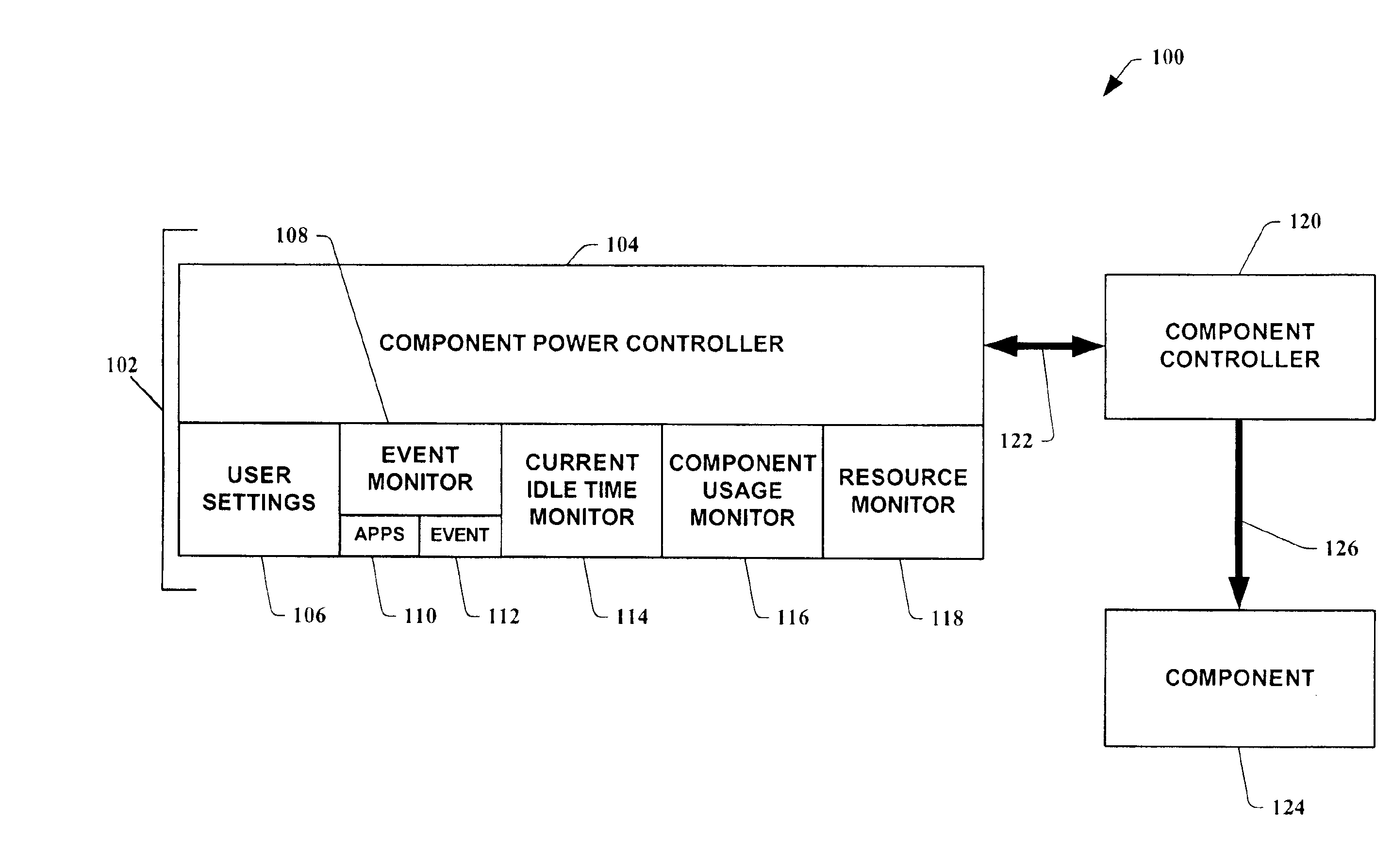
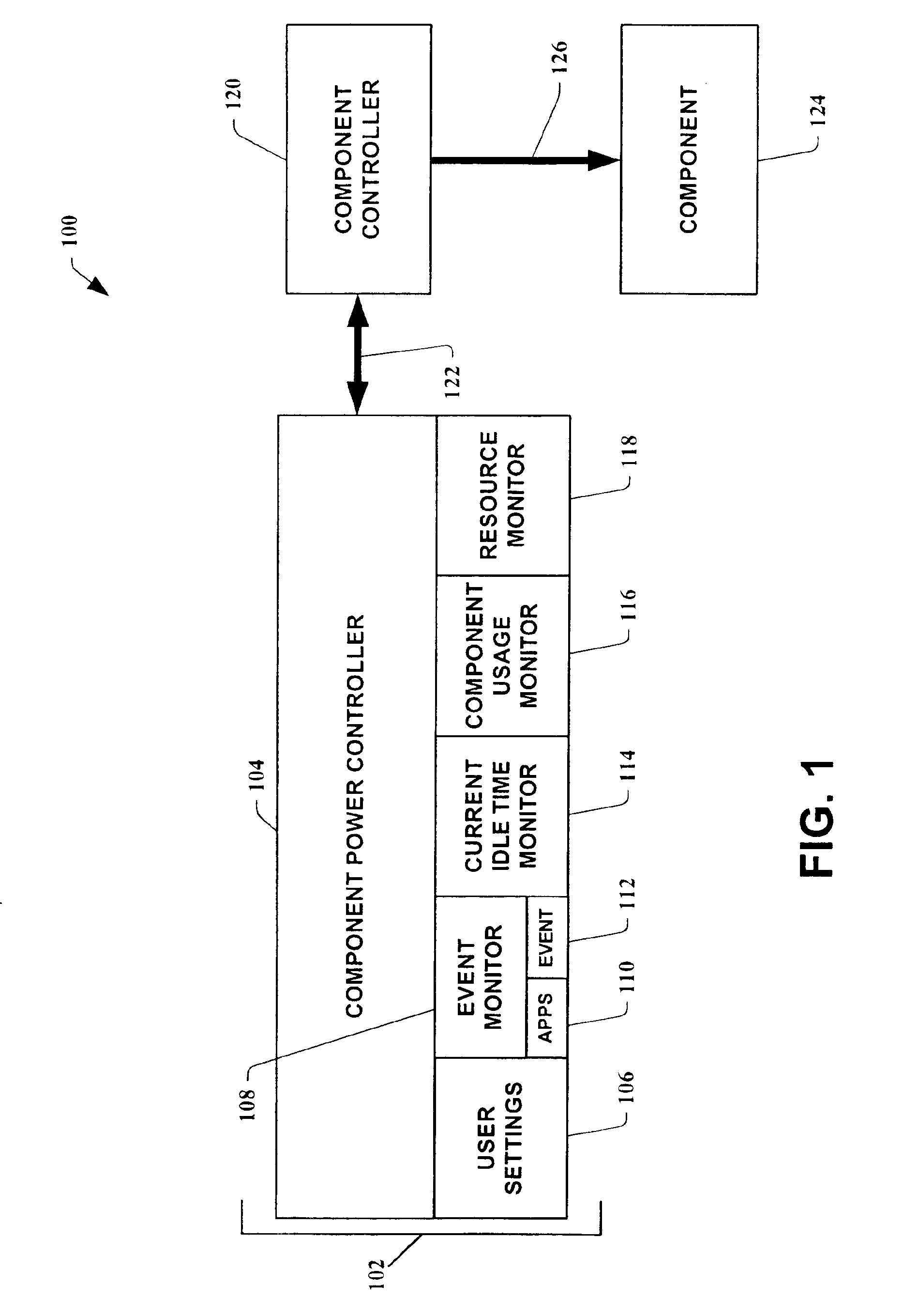
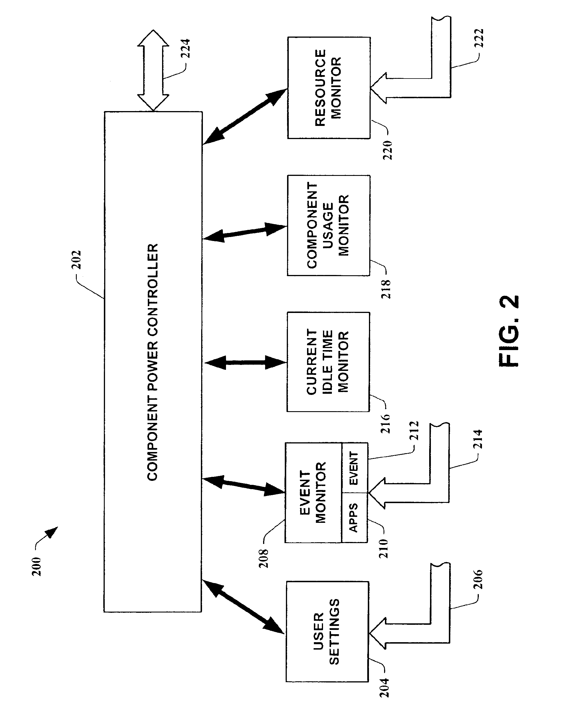
[0022]The present invention is now described with reference to the drawings, wherein like reference numerals are used to refer to like elements throughout. In the following description, for purposes of explanation, numerous specific details are set forth in order to provide a thorough understanding of the present invention. It may be evident, however, that the present invention may be practiced without these specific details. In other instances, well-known structures and devices are shown in block diagram form in order to facilitate describing the present invention.

[0023]As used in this application, the term “computer component” is intended to refer to a computer-related entity, either hardware, a combination of hardware and software, software, or software in execution. For example, a computer component may be, but is not limited to being, a process running on a processor, a processor, an object, an executable, a thread of execution, a program, and / or a computer. By way of illustrat...


PUM


Abstract

Dynamic power controller apparatus, systems and methods are provided which utilize system and user data to control power to components. The present invention employs dynamically controlled idle timeout values which are based, in part, on the historical use of the component. It can also employ user settings, event occurrences and available resources of a system to dynamically control the power to one of the system's components or a remote component. In an instance of the present invention related to hard disk power control, it is employed in an operating system's kernel where disk idleness is monitored. When the hard disk's idle time meets a dynamically computed power control idle timeout, the disk driver is commanded to power down the device.

Description

TECHNICAL FIELD[0001]The present invention relates generally to power control, and more particularly to apparatus, systems and methods facilitating dynamic power control of computer related devices.BACKGROUND OF THE INVENTION[0002]Computers have pervaded most aspects of our daily lives. Their usage has enabled great strides in our society in many different areas. As computer technology advances, the computing devices become more powerful and, at the same time, smaller in size. Business people, scientists and every day users have become attached to the usefulness of their computers to the point that they demand that the devices be made more portable so they can be carried at all times. This has led to development of “laptop” computers followed by even smaller “handheld” devices. The computing power in these portables often rivals much larger “desktop” computers. However, the desktop computers are normally plugged into an “infinite” power source, namely the local energy company via an...

Claims


Application Information

Patent Timeline
Patent Type & Authority Patents(United States)
IPC IPC(8): G06F1/26G06F1/32G06F19/00
CPCG06F1/3228G06F1/3287Y02B60/32Y02B60/1282Y02D10/00Y02D30/50
Inventor HOLLE, MATTHEW H.
Owner MICROSOFT TECH LICENSING LLC
Why Eureka
Try Eureka