
Urological electrosurgical resectoscope

a resectoscope and electrosurgical technology, applied in the field of urological electrosurgical resectoscope, can solve problems such as problems such as problems, defects or damage, and problems such as the problem of hf loaded contacts, and achieve the effect of avoiding defects or damage, avoiding the occurrence of defects, and avoiding the occurrence of hf load contacts

Inactive Publication Date: 2005-05-17
OLYMPUS WINTER & IBE
View PDF6 Cites 33 Cited by
  • Summary
  • Abstract
  • Description
  • Claims
  • Application Information

AI Technical Summary

Benefits of technology

The present invention is about a resectoscope that allows for easy attachment of an electrode support to a slide block without interfering with the electrical connection. The design of the invention allows for a strong attachment of the electrode support using various methods such as clamping, locking, or firmly retaining detent connections. The proximal configuration of the attachment element ensures complete insertion of the electrode support and allows for tighter pivoting of the stiff end segment. The invention also includes a limit stop to accurately position the electrode support. Overall, the invention improves the reliability and accuracy of the resectoscope's electrical connection.

Problems solved by technology

Problems are encountered as regards the appropriate contact between the electrical conductor feeding the electrode and the slide block site it touches.
HF loaded contacts are problematical and are susceptible to defects or damage, such as scorching.
However, the known design of the above species does entail drawbacks.
As a result the electrode support lacks mechanical strength in this region.
If affixation takes place by means of a slide block entering a groove and acting on the electrode support, then the groove may only be very shallow and consequently the reliability of affixation is considerably reduced.
However, the main block being required to be of moderate length on technical grounds, large pivoting must take place over a short path.
Unfortunately, the considerable length of the rigid end region of the known electrode supports hampers such motion.
Moreover, assembly may be defective if the electrode support was insufficiently inserted and thereupon was fixed in place.

Method used


Image

  • Urological electrosurgical resectoscope
  • Urological electrosurgical resectoscope

Examples


Embodiment Construction

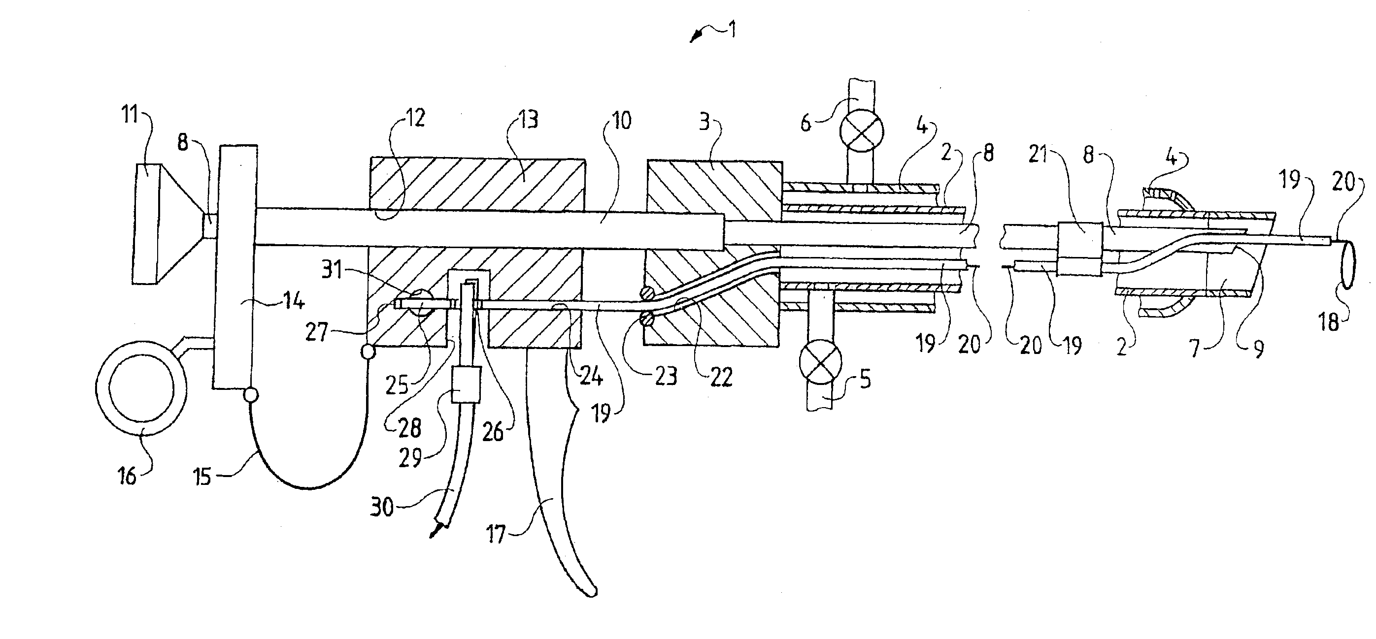
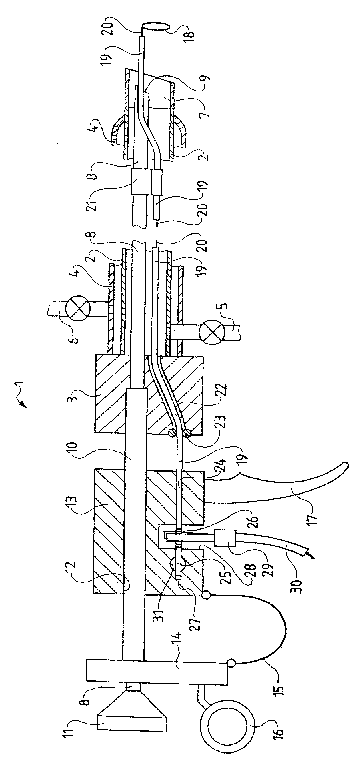
[0016]The shown resectoscope 1 comprises a stem tube 2 that is affixed by its proximal end to a main block 3. In manner not shown in the drawing, the stem tube 2 may be detachably mounted by means of a conventional coupling element on the main block 3. An external tube 4 encloses the stem tube 2 and also is mounted on the main block 3, again in conventional manner, using a coupling element (not shown). The inside of the stem tube 2 serves in conventional manner as an intake duct for permanent irrigation and, as shown in the drawing, is externally accessible through a valve-fitted hookup 5, which may be connected to a hose. Another and similar hookup 6 connecting a further hose is connected to the annular gap between the stem tube 2 and the external tube 4 and serves as the return duct.

[0017]The two tubes 2 and 4 are conventionally metallic. The distal end zone of the stem tube 2 is conventionally insulating and illustratively in the form of a ceramic element 7.

[0018]An optics 8 runs...


PUM


Abstract

A urological resectoscope having an axially extending shaft tube, the proximal end thereof being fixed to a main body. A sliding body is proximally positioned in relation to the main body, and can slide in a parallel manner in relation to the axis thereof. The sliding body includes a receiver, a fixing device and a contacting device. An electrode that can be subjected to a high frequency, including a rigid electrode carrier having one external, insulated conductive wire, can be positioned in the resectoscope such that it can axially slide beyond the distal end of the shaft tube. In the assembly position, the electrode carrier extends through the shaft tube and the main body into the receiver, and can be fixed by the fixing device and contacted by the contacting device. The fixing device is proximally arranged in relation to the contacting device on the sliding body.

Description

BACKGROUND OF THE INVENTION[0001]Urological resectoscopes are primarily used for prostate resections, though, depending on the particular design, they also may be used for other surgical purposes. Herein the concept of “resectoscope” denotes endoscopic instruments wherein an optics and an electrode support, together with a distal electrode, are configured in a stem tube and wherein the electrode support jointly with the electrode is configured in an axially displaceable manner. The support is affixed at its proximal end to a resectoscope slide block with which it makes electric contact, the slide block being axially displaceable by manually driving a grip in order to axially displace the electrode.[0002]During prostate resection, the distal stem tube end of the resectoscope is advanced through the urethra inside the prostrate. When hf is applied to the electrode, the electrode may be advanced and retracted by manually driving the slide block in order to cut tissue. In general, the e...

Claims


Application Information

Patent Timeline
Patent Type & Authority Patents(United States)
IPC IPC(8): A61B18/14
CPCA61B18/149
Inventor BROMMERSMA, PIETERNUSSBAUM, FELIX
Owner OLYMPUS WINTER & IBE
Learn More