Belt attachment device and method

a technology of belt attachment and belt, which is applied in the direction of belt fastening, belt/chain/gearing, transportation and packaging, etc., can solve the problems of difficult removal and replacement of conveyor belts, failure of bonding created in this type of attachment, etc., and achieve the effect of convenient mounting of items

Inactive Publication Date: 2005-05-24
PFLOW INDS
View PDF25 Cites 35 Cited by
  • Summary
  • Abstract
  • Description
  • Claims
  • Application Information

AI Technical Summary

Benefits of technology

[0004]The present invention provides a conveyor belt assembly that facilitates mounting items to the belt. The assembly includes a flexible belt body with a first (outer) surface and a second (inner) surface. A plurality of flexible teeth (e.g. made of ru

Problems solved by technology

However, the bond created in this type of attachment often fails under heavy loads.
Another issue with conveyor belt systems is facilitating the removal and repl

Method used


Image

  • Belt attachment device and method
  • Belt attachment device and method
  • Belt attachment device and method

Examples


Embodiment Construction

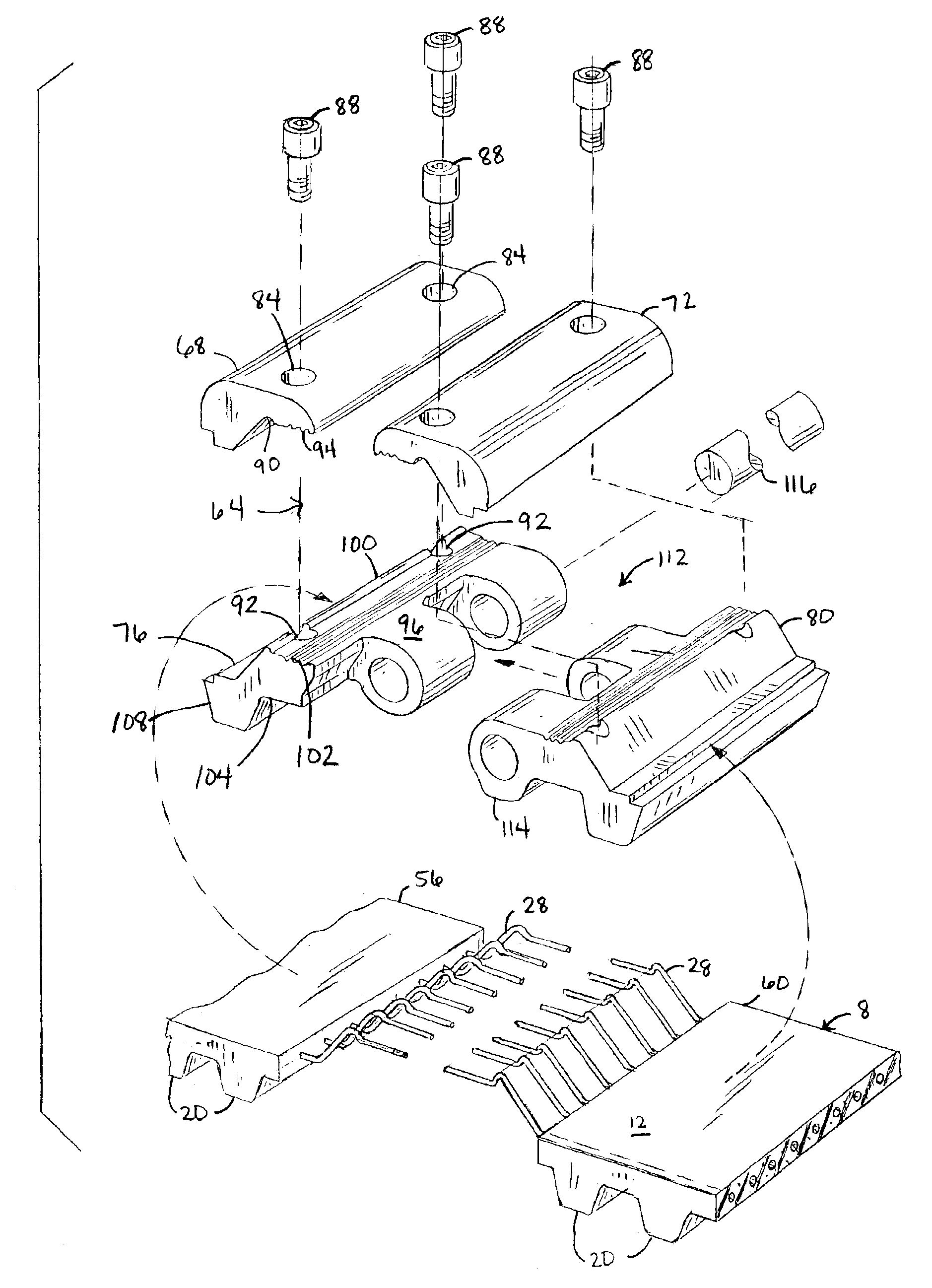
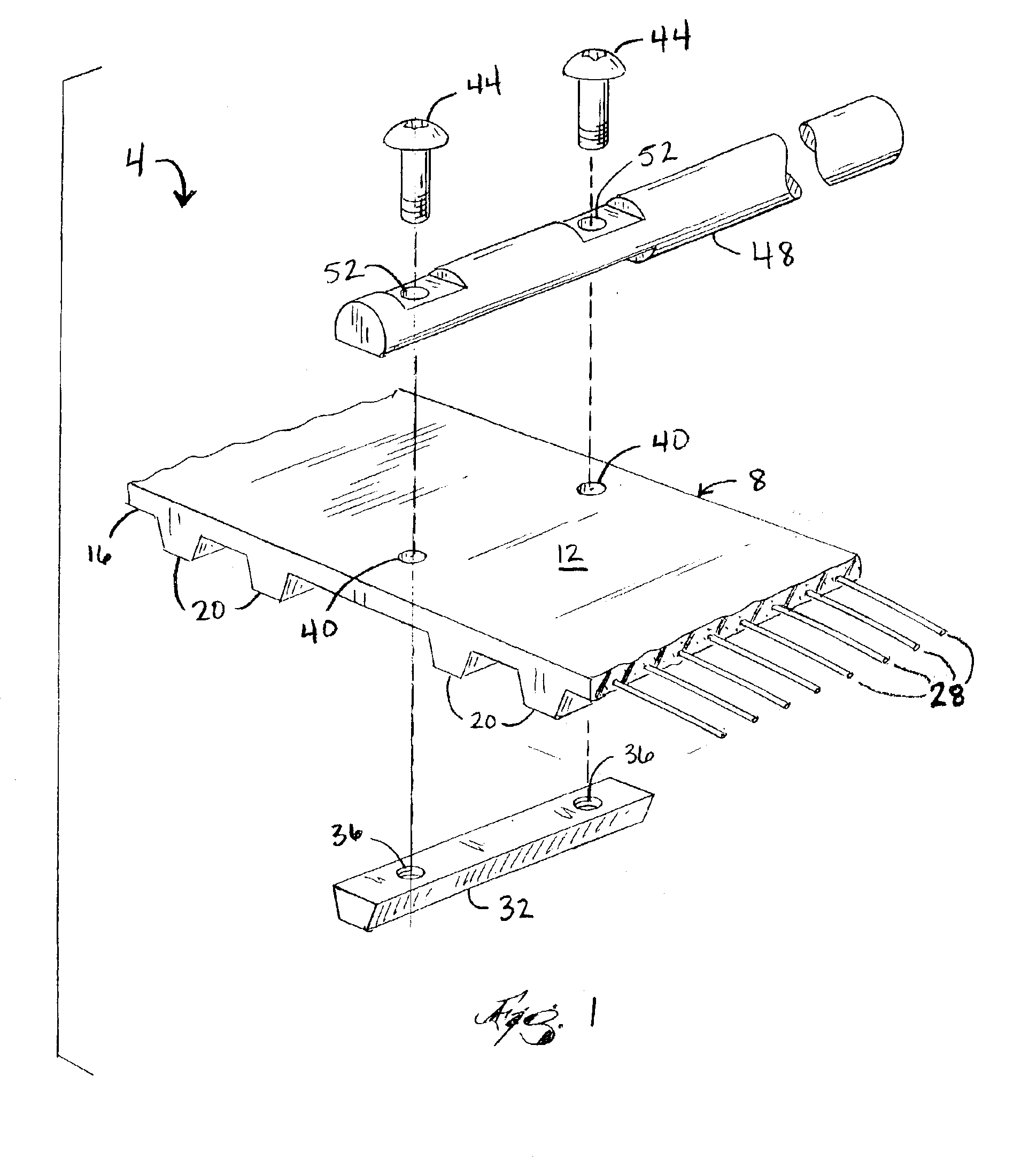
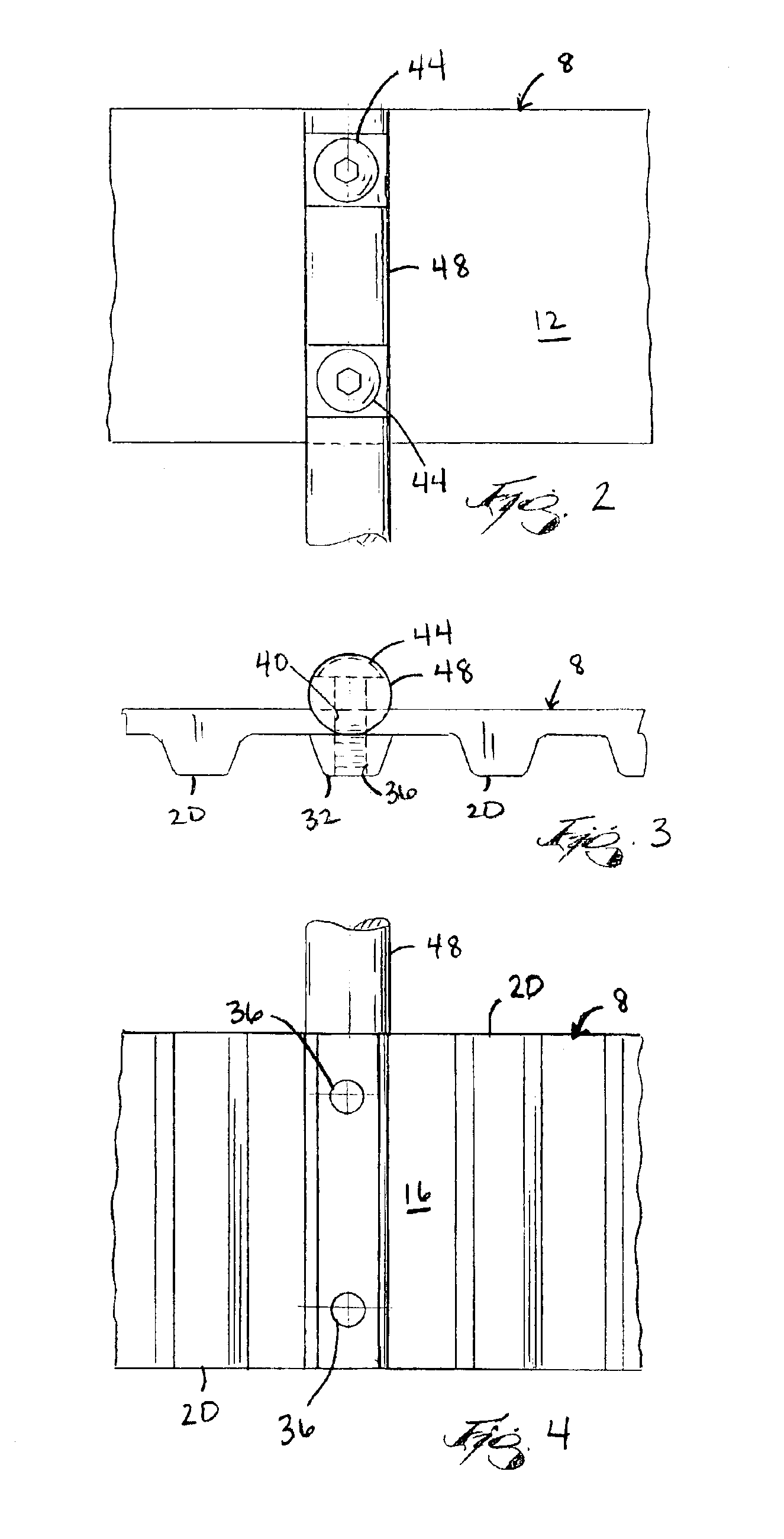
[0020]FIG. 1 illustrates a portion of a conveyor belt assembly 4 according to one aspect of the present invention. The conveyor belt assembly 4 includes a flexible belt body 8 with a first surface 12 and second surface 16. It should be understood that the terms “first” and “second” are used for convenience to refer to the outer and inner surfaces of the belt. In the embodiment illustrated in FIGS. 1-4, the flexible belt body 8 is an endless belt. It is understood, however, that in other embodiments, such as the embodiment illustrated in FIGS. 5-7, the flexible belt body 8 may have discrete ends.

[0021]As shown in FIG. 1, the first surface 12 of the belt body 8 is a smooth, non-segmented surface. A plurality of flexible teeth 20 are formed with the belt body 8 on the second surface 16. The belt body 8 and teeth 20 are formed of a resilient material, such as rubber. It is understood by those skilled in the art that the belt body 8 and teeth 20 may be formed of any suitable flexible mat...


PUM


Abstract

A conveyor belt assembly including a flexible belt body with a plurality of spaced flexible teeth and at least one hardened tooth coupled to the belt body. The flexible belt body and flexible teeth comprise a resilient material. The hardened tooth comprises hardened plastic or metal. The flexible belt body also includes at least one reinforcing member within the belt body. A guide member is coupled to the flexible belt body and the hardened tooth to assist in transporting objects on the conveyor belt assembly. A pivotable clamping device clamps the ends of the belt body together to form a continuous belt. The clamping device clamps the reinforcing member to ensure a strong connection.

Description

FIELD OF THE INVENTION[0001]The invention relates to conveyor belts, and more particularly to methods of attaching objects to conveyor belts.BACKGROUND OF THE INVENTION[0002]It is known in industries utilizing conveyor belt systems to mechanically attach items, such as baskets or bins, to conveyor belts to assist in moving objects from one point to another. The prevalent method of making attachments to conveyor belts is to glue or “weld” the attachments onto the belt. However, the bond created in this type of attachment often fails under heavy loads.[0003]Another issue with conveyor belt systems is facilitating the removal and replacement of conveyor belts to replace worn or broken segments of the belt. In systems where an endless belt is used, an “endless” belt is commonly formed by splicing two ends of a belt together by serrating the edges and gluing the ends together. By gluing the ends together, it becomes difficult to remove and replace a conveyor belt. Often, the conveying ma...

Claims


Application Information

Patent Timeline
IPC IPC(8): B65G17/30B65G15/30B65G15/52B65G17/42F16G3/00F16G3/02
CPCB65G15/52F16G3/02F16G3/00B65G17/42
Inventor WEBSTER, MARK R.SCHMIDT, CRAIG S.
Owner PFLOW INDS
Why Eureka
Try Eureka