Female Snap Button

a female and snap button technology, applied in the field of female snap buttons, can solve problems such as reducing size, and achieve the effects of easy supply of elastic deformation performance, easy attachment and detachment of protruding parts, and increased elastic deformation of the engaging portion in the radial direction

Active Publication Date: 2017-11-16
YKK CORP
View PDF3 Cites 0 Cited by
  • Summary
  • Abstract
  • Description
  • Claims
  • Application Information

AI Technical Summary

Benefits of technology

[0009]In an embodiment of the present invention, an inner diameter of the socket ring is gradually increased from an intermediate point in the axial direction of the engaging portion to one end and other end in the axial direction of the engaging portion. Thus, the engaging portion of the socket ring has both ends in the axial direction, which are positioned radially more outward than the intermediate point. This facilitates attachment and detachment of the protrusion of the male snap button to and from the engaging portion of the socket ring. Here, the “intermediate point” refers to a point located just in an intermediate position between the one side end and the other side end in the axial direction of the engaging portion or a point near the intermediate position.
[0010]In one embodiment of the present invention, the holding portion includes a lower holding portion supporting the bottom portion side in the flange portion of the socket ring, a side holding portion rising from a radially outer side of the lower holding portion, and an upper holding portion extending radially inward from an end portion of the side away from the lower holding portion in the side holding portion, wherein the engaging portion protrudes downwardly toward the bottom portion side and below the lower holding portion. In this way, the engaging portion of the socket ring protrudes downwardly toward the bottom portion side of the male snap body and below the lower holding portion, so that it will be easy to pro

Problems solved by technology

However, the spring having the circular cross section of the female snap button as described above cannot reduce the size, i.e., the diameter so much, in order to maintain elastic deformation performance and holding force for engaging with the prot

Method used


Image

  • Female Snap Button
  • Female Snap Button
  • Female Snap Button

Examples


Embodiment Construction

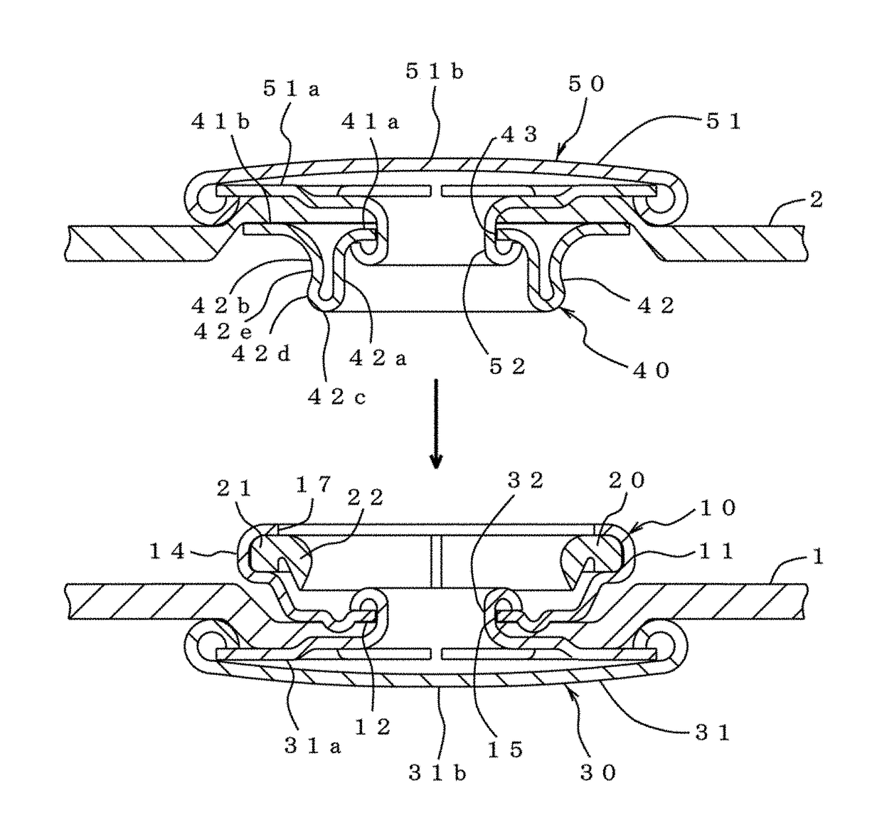
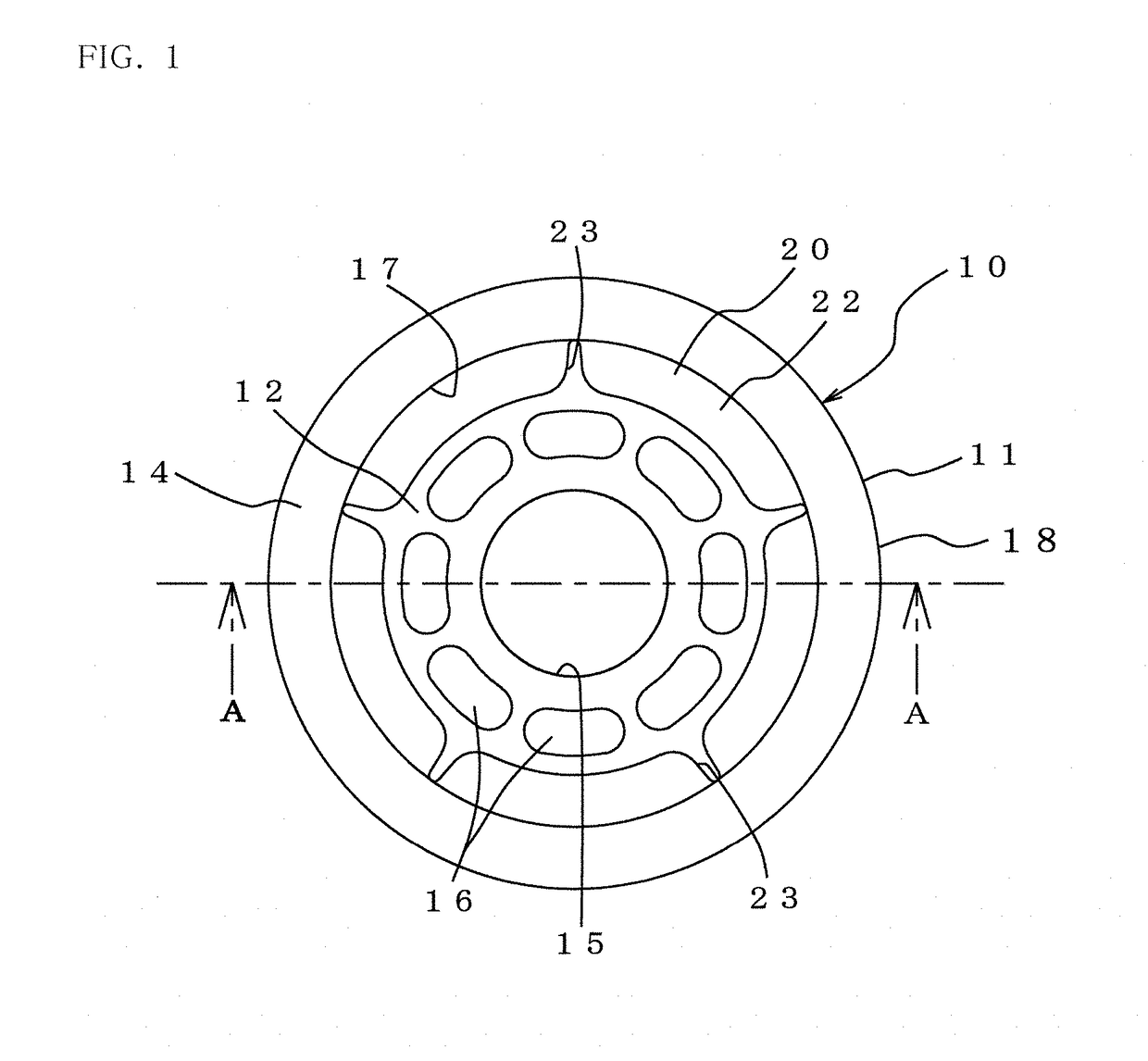
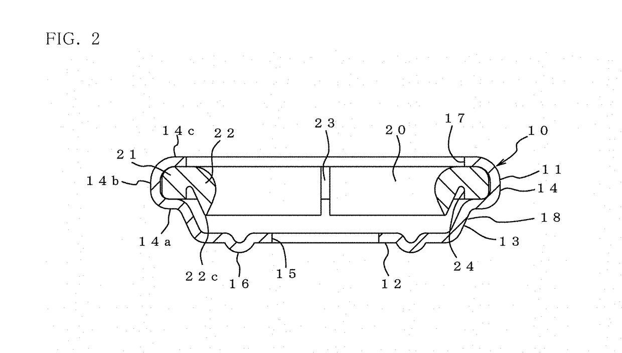
[0024]Preferred embodiments of the present invention will be described below with reference to the accompanying figures, but the present invention is not limited to these embodiments, and appropriate modifications and the like can be made within the scope of the claims and the equivalent scope. FIG. 1 is a plan view of a female snap button (hereinafter simply referred to as a “female snap”) 10 according to an embodiment of the present invention. FIG. 2 is a cross-sectional view taken along the line A-A of FIG. 1. The female snap 10 is composed of a metallic female snap body 11 and a resinous annular socket ring 20 housed in the female snap body 11. The female snap body 11 is formed by drawing a metal plate or the like, and comprises a bottom portion 12 and a side wall 18 rising upwardly in the axial direction from a radially outer end (peripheral edge) of the bottom portion 12 (it should be noted that the up and down direction regarding the female snap 10 is based on a paper surface...


PUM


Abstract

A snap button includes a female snap body and a socket ring. The female snap body includes a bottom portion and a side wall rising from a peripheral edge of the bottom portion, the side wall provided with a holding portion for holding the socket ring. The socket ring includes a flange portion arranged radially outward and held by the holding portion and an engaging portion arranged radially inside the flange portion. The engaging portion protrudes downwardly toward the bottom portion side of the female snap body and below the flange portion, in the axial direction of the socket ring. An inner diameter of the socket ring may be gradually increased from an intermediate point in the axial direction of the engaging portion to one end and other end in the axial direction of the engaging portion. The engaging portion of the socket ring may be provided with a plurality of slits along the radial direction in the circumferential direction.

Description

TECHNICAL FIELD[0001]The present invention relates to a female snap button to be attached to and detached from a male snap button.BACKGROUND ART[0002]Snap buttons which attaches and detaches female snap buttons and male snap buttons are widely used for clothes, bags, and the like. The male snap button generally has a protrusion having a tip with a slightly larger diameter. By engaging and disengaging the protrusion with and from a protrusion receiving portion of the female snap button, the female snap button and the male snap button are connected and disconnected. There is known one type of the female snap button, in which an annular spring as a separate member is incorporated in a metallic female snap body, as shown in FIG. 6 of Japanese Utility Model Publication No. S63-90 A1. Such a spring is generally formed by cutting and bending a metal or resin wire member having a circular cross section. The female snap body is provided with a spring holding portion for holding the spring. W...

Claims


Application Information

Patent Timeline
IPC IPC(8): A44B17/00
CPCA44B17/0005A44B17/0076A44B17/00A44B17/0011A44B17/0052Y10T24/45874Y10T24/45775A44B17/0064
Inventor HAYASHI, DAISUKE
Owner YKK CORP
Why Eureka
Try Eureka