Substrate holding unit, exposure apparatus having same, exposure method, method for producing device, and liquid repellent plate

a technology for holding units and substrates, applied in photomechanical equipment, instruments, printing, etc., can solve the problems of difficult to match the substrate surface with respect to the image plane of the projection optical system, insufficient focus margin, and easy so as to suppress the deformation of the plate and/or the base member, and easy to attach and detach

Inactive Publication Date: 2007-08-02
NIKON CORP
View PDF19 Cites 225 Cited by
  • Summary
  • Abstract
  • Description
  • Claims
  • Application Information

AI Technical Summary

Benefits of technology

[0008] In order to achieve the objects as described above, the present invention adopts the following constructions corresponding to FIGS. 1 to 17 as illustrated in embodiments. However, parenthesized symbols affixed to respective elements merely exemplify the elements by way of example, with which it is not intended to limit the respective elements.
[0009] According to a first aspect of the present invention, there is provided a substrate-holding unit (PH) which holds a process substrate (P); comprising a base member (PHB); a first holding portion (PH1) which is formed in the base member (PHB) and which attracts and holds the process substrate (P); and a second holding portion (PH2) which is formed in the base member (PHB) and which attracts and holds a plate (T) in the vicinity of the process substrate (P) attracted and held by the first holding portion (PH1).
[0010] According to the present invention, the plate, which is arranged in the vicinity of the process substrate attracted and held by the first holding portion, can be easily attached and detached with respect to the second holding portion. Therefore, for example, when the plate is deteriorated and / or damaged, only the plate can be exchanged with new one with ease. In this construction, the plate is attracted and held by the second holding portion. Therefore, it is possible to avoid any application of the local force, for example, to the plate and the base member. Therefore, it is possible to suppress the deformation of the plate and / or the base member. In this patent application, the term “process substrate” means a substrate to which various process treatments including the exposure process are to be applied. The term “process substrate” includes those obtained by coating, with a photoresist as the photosensitive material, the substrate to be used for various ways of use, including, for example, the semiconductor wafer for producing the semiconductor device, the substrate for the liquid crystal display (LCD), the ceramic wafer for the thin film magnetic head, and the master plate or the master disk (synthetic silica glass, silicon wafer) for the mask or the reticle to be used for the exposure apparatus.
[0011] According to a second aspect of the present invention, there is provided an exposure apparatus (EX) which exposes a process substrate (P) by projecting an image of a pattern onto the process substrate (P), the exposure apparatus comprising: a first plate (T1); a second plate (T2); and a substrate-holding unit (PH) including a first holding portion (PH1) which attracts and holds the process substrate (P), a second holding portion (PH2) which attracts and holds the first plate (T1) in the vicinity of the process substrate (P) attracted and held by the first holding portion (PH1), and a third holding portion (PH3) which attracts and holds the second plate (T2) in the vicinity of the process substrate (P) attracted and held by the first holding portion (PH1).
[0012] According to the present invention, the first and second plates, which are arranged in the vicinity of the process substrate attracted and held by the first holding portion, can be easily attached and detached with respect to the third holding portion. Therefore, for example, when the first and the second plates are damaged, they can be exchanged with new plates with ease. It is also possible to exchange only any one of the first plate and the second plate. It is possible to exchange only an arbitrary plate of the plurality of plates. In this construction, the first and second plates, which forms the upper surface of the substrate-holding unit, are attracted and held by the second and third holding portions, respectively. Therefore, it is possible to prevent, for example, the first and second plates and the base member from any application of the local force. Therefore, it is possible to suppress the deformation of the first plate, the second plates and / or the base member.
[0013] According to the present invention, there is provided a method for producing a device, comprising using the exposure apparatus (EX) as described above. According to the present invention, the exposure process and the measurement process can be performed satisfactorily. Therefore, it is possible to provide the device having desired performance.

Problems solved by technology

If the depth of focus δ is too narrowed, it is difficult to match the substrate surface with respect to the image plane of the projection optical system.
It is feared that the focus margin is insufficient during the exposure operation.
Therefore, the member (or any coating thereof), which forms the upper surface of the substrate stage PST′, is easily deteriorated and / or damaged.
When the deterioration and / or the damage is caused as described above, an inconvenience arises such that the rate of operation of the exposure apparatus is lowered due to the execution of the maintenance operation such as the repair and / or the exchange of the substrate stage PST′.
In such a situation, a possibility arises such that the substrate stage cannot hold or retain the substrate satisfactorily.
Therefore, there is such a possibility that the flatness of the supported substrate may be consequently deteriorated.
Further, for example, there is also such a possibility that the following inconvenience may arise.

Method used


Image

  • Substrate holding unit, exposure apparatus having same, exposure method, method for producing device, and liquid repellent plate
  • Substrate holding unit, exposure apparatus having same, exposure method, method for producing device, and liquid repellent plate
  • Substrate holding unit, exposure apparatus having same, exposure method, method for producing device, and liquid repellent plate

Examples


first embodiment

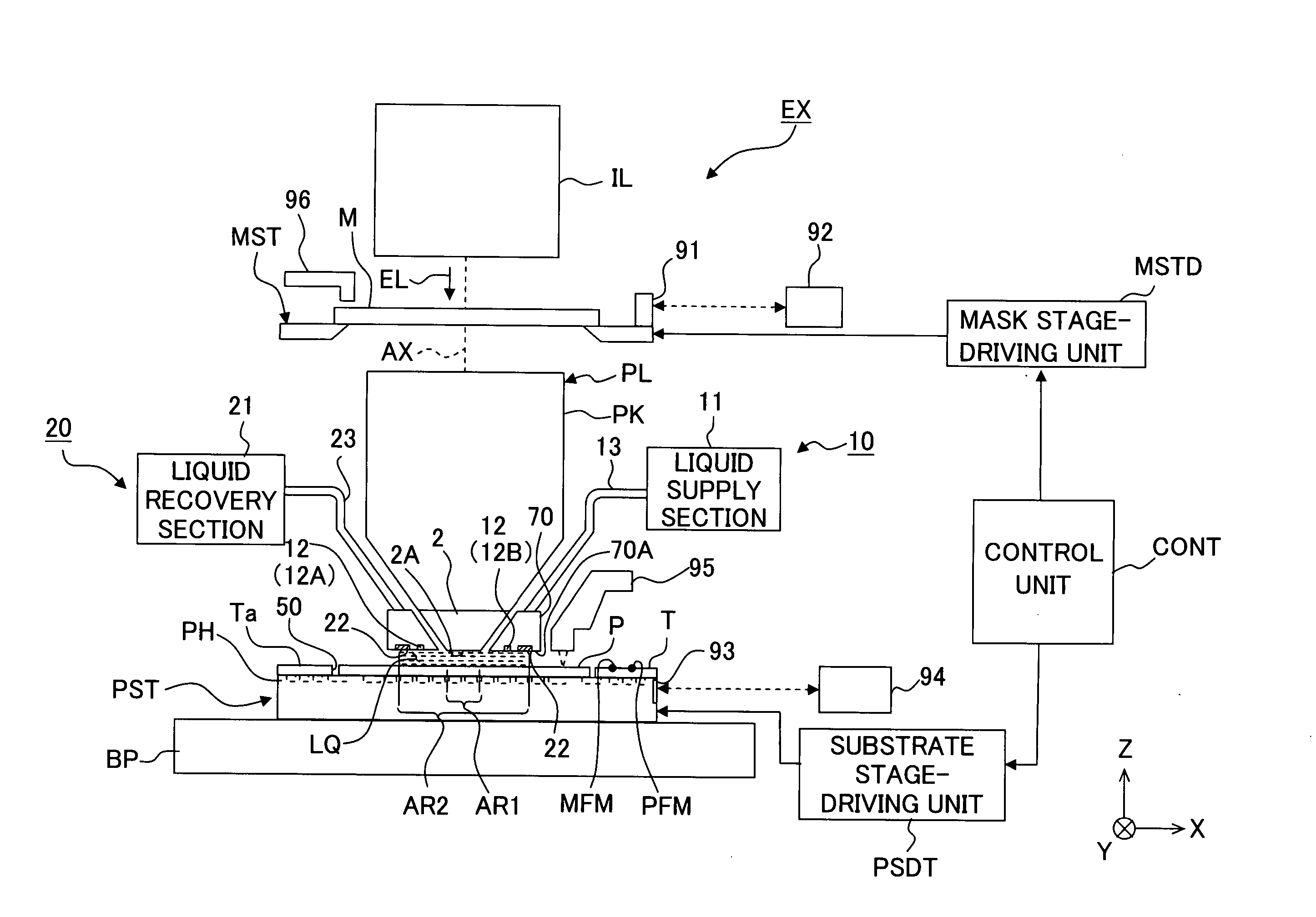
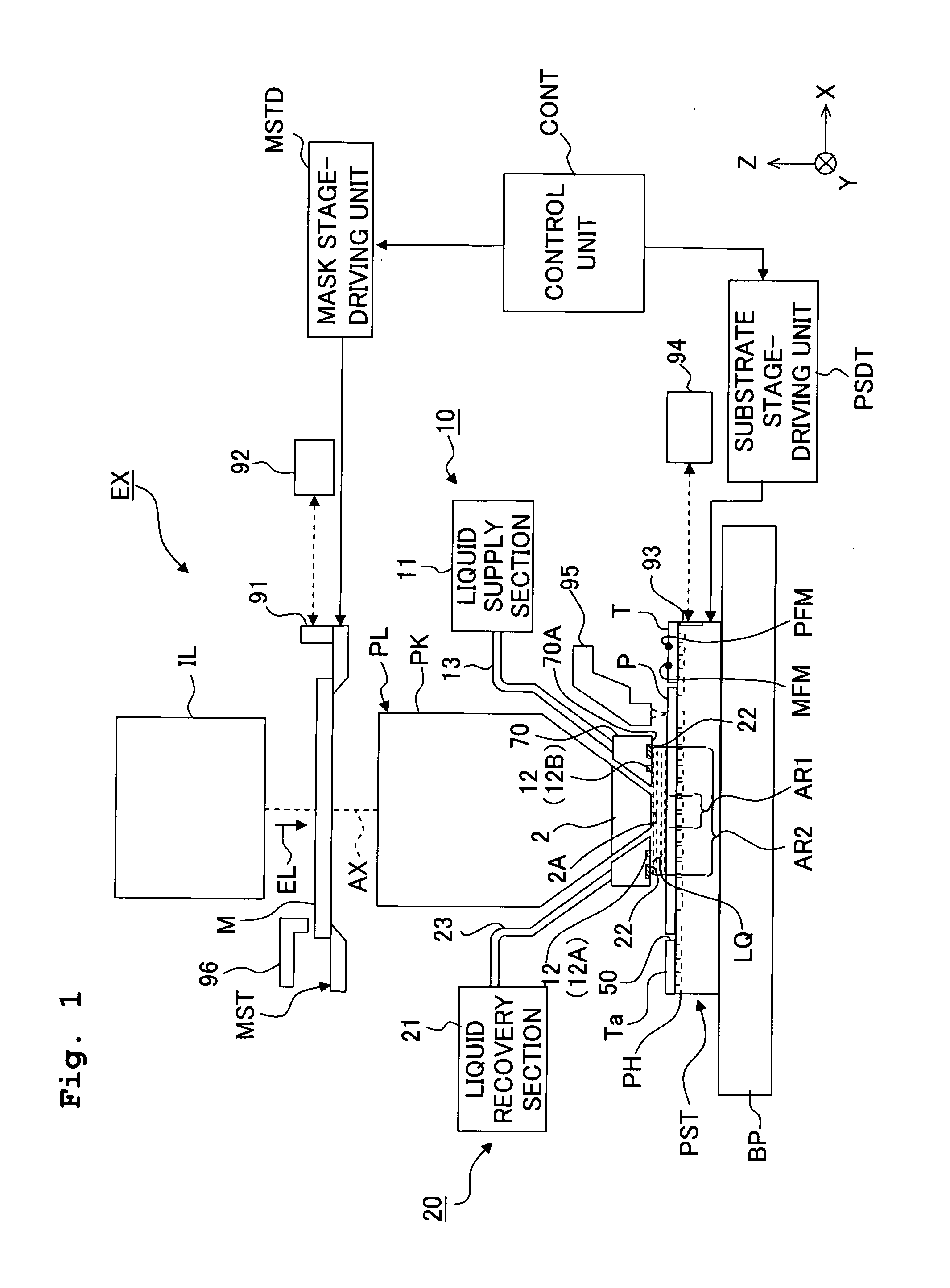
[0045]FIG. 1 shows a schematic arrangement illustrating a first embodiment of the exposure apparatus according to the present invention. With reference to FIG. 1, the exposure apparatus EX includes a mask stage MST which is movable while supporting a mask M, a substrate stage PST which has a substrate holder (substrate-holding unit) PH which holds or retains a substrate and which is capable of moving the substrate P held by the substrate holder PH, an illumination optical system IL which illuminates, with an exposure light beam EL, the mask M supported by the mask stage MST, a projection optical system PL which projects an image of a pattern of the mask M illuminated with the exposure light beam EL onto the substrate P supported by the substrate stage PST, and a control unit CONT which integrally controls the operation of the entire exposure apparatus EX.

[0046] The exposure apparatus EX of the embodiment of the present invention is the liquid immersion exposure apparatus in which t...

second embodiment

[0144] Next, an explanation will be made about a second embodiment of the substrate stage PST (substrate holder PH). In the following explanation, the constitutive components, which are the same as or equivalent to those of the first embodiment described above, are designated by the same reference numerals, any explanation of which will be simplified or omitted. Modified embodiments, which are common to those of the first embodiment, will be omitted from the explanation as well.

[0145] With reference to FIG. 10, an intermediate circumferential wall portion 162, which is substantially annular as viewed in a plan view and which is provided to surround the second circumferential wall portion 62, is provided on the upper surface of the base member PHB between the second circumferential wall portion 62 and the third circumferential wall portion 63. The intermediate circumferential wall portion 162 is formed to be slightly lower than the second support portion 66 or have approximately the...

third embodiment

[0154]FIG. 11 shows a third embodiment. Constructions and modified embodiments, which are common to those of the first and second embodiments, will be explained in a simplified manner or omitted from the explanation. With reference to FIG. 11, a plate member T, which is held by the second holding portion PH2, has a surface (first surface) Ta which is substantially flush with the surface Pa of the substrate P held by the first holding portion PH1, a side surface Tc which is opposite to or facing the side surface Pc of the substrate P, a liquid-receiving surface Tg which is provided along the side surface Tc and which is substantially parallel to the surface Ta, and an opposing surface (second surface) Tj which is opposite to or facing the back surface Pb of the substrate P at the circumferential edge portion of the substrate P held by the first holding portion PH1. The surface Ta of the plate member T is formed to surround the surface Pa of the substrate P in the same manner as in th...


PUM

PropertyMeasurementUnit
sizeaaaaaaaaaa
refractive indexaaaaaaaaaa
wavelengthaaaaaaaaaa

Abstract

A substrate holder includes a base; a first holding portion which is formed on the base and which attracts and holds a substrate; and a second holding portion which is formed on the base and which attracts and holds a plate member in the vicinity of the substrate attracted and held by the first holding portion. In an exposure apparatus including such a substrate holder, the plate can be exchanged easily, thereby making the maintenance of the apparatus easy. Consequently, such an exposure apparatus is suitable for immersion exposure.

Description

TECHNICAL FIELD [0001] The present invention relates to a substrate-holding unit for holding a process substrate, an exposure apparatus provided with the same, an exposure method, a method for producing a device, and a liquid-repelling plate. BACKGROUND ART [0002] Semiconductor devices and liquid crystal display devices are produced by the so-called photolithography technique in which a pattern formed on a mask is transferred onto a photosensitive substrate. The exposure apparatus, which is used in the photolithography step, includes a mask stage for supporting the mask and a substrate stage for supporting the substrate. The pattern on the mask is transferred onto the substrate via a projection optical system while successively moving the mask stage and the substrate stage. In recent years, it is demanded to realize the higher resolution of the projection optical system in order to respond to the further advance of the higher integration of the device pattern. As the exposure wavele...

Claims


Application Information

Patent Timeline
Patent Type & Authority Applications(United States)
IPC IPC(8): G03B27/58G03F7/20G03F9/00H01L21/027H01L21/68H01L21/683
CPCG03F7/70341G03F7/70425H01L21/6838G03F7/707G03F7/2041H01L21/0274G03F7/70866G03F7/70716
Inventor SHIBAZAKI, YUICHI
Owner NIKON CORP
Why Eureka
Try Eureka