Tissue retractor adapted for the attachment of an auxiliary element

Inactive Publication Date: 2001-03-06
LAB ENG & MFG
View PDF23 Cites 249 Cited by
  • Summary
  • Abstract
  • Description
  • Claims
  • Application Information

AI Technical Summary

Problems solved by technology

These retractors, however, only provide separation at two opposed locations.
While such an approach provides more tissue contacts, it has not gained wide acceptance.
In addition, the clearance passage through the c

Method used


Image

  • Tissue retractor adapted for the attachment of an auxiliary element
  • Tissue retractor adapted for the attachment of an auxiliary element
  • Tissue retractor adapted for the attachment of an auxiliary element

Examples


Example

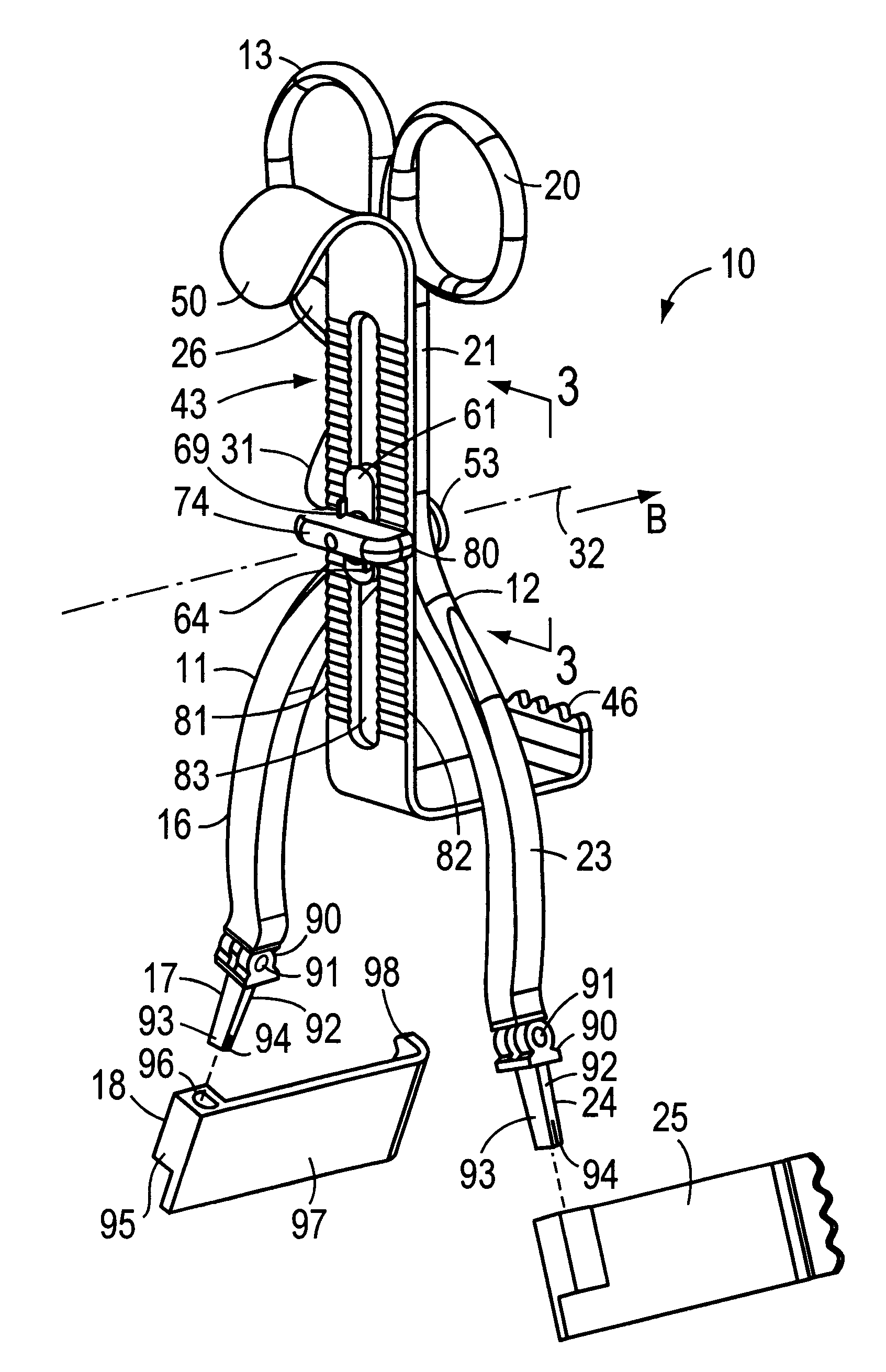
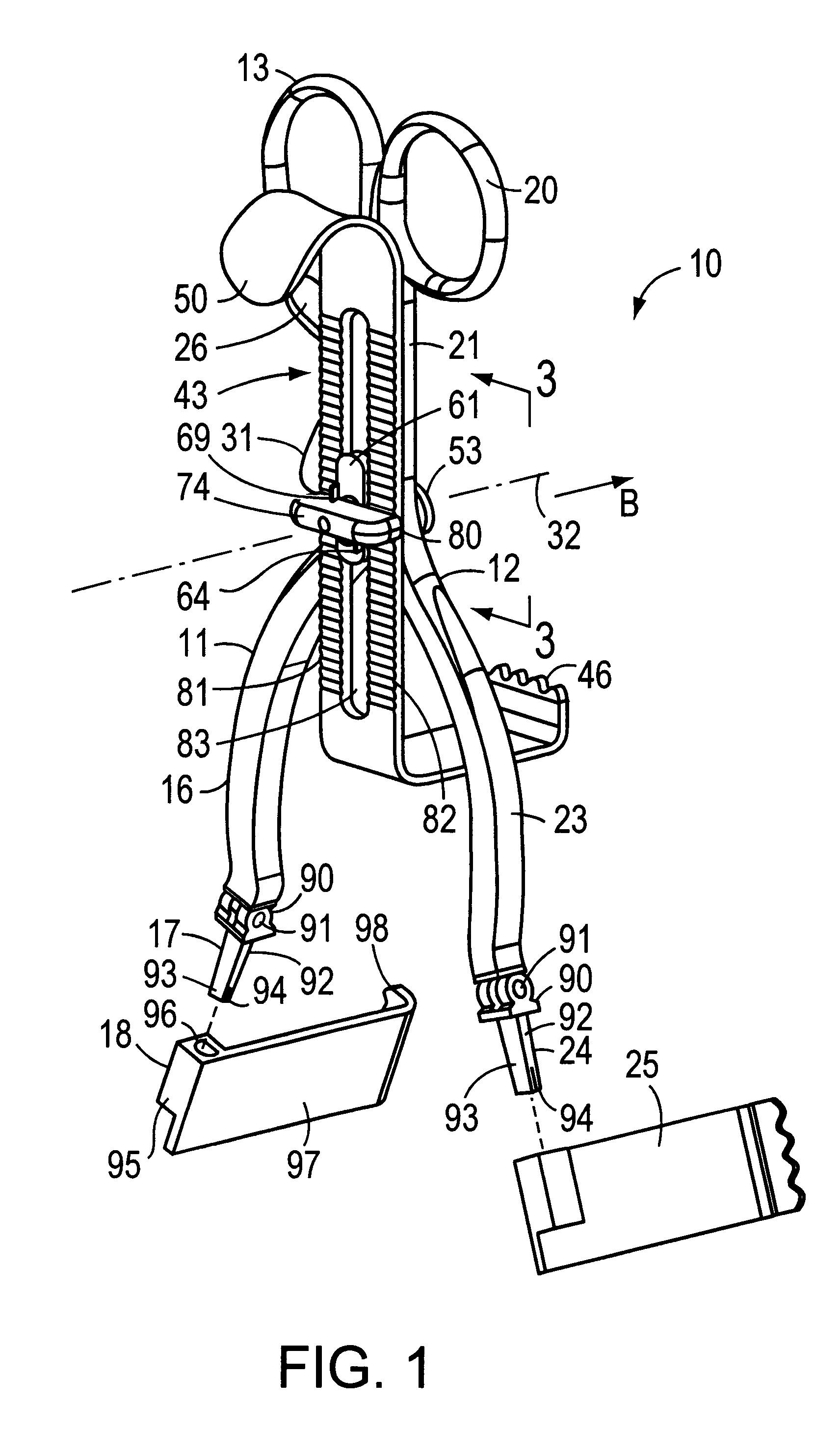
FIG. 1 depicts a soft tissue retractor 10 that incorporates this invention. The basic structure of the retractor 10 comprises a first arm 11 and second arm 12 that are adapted to rotate about a pivot axis.

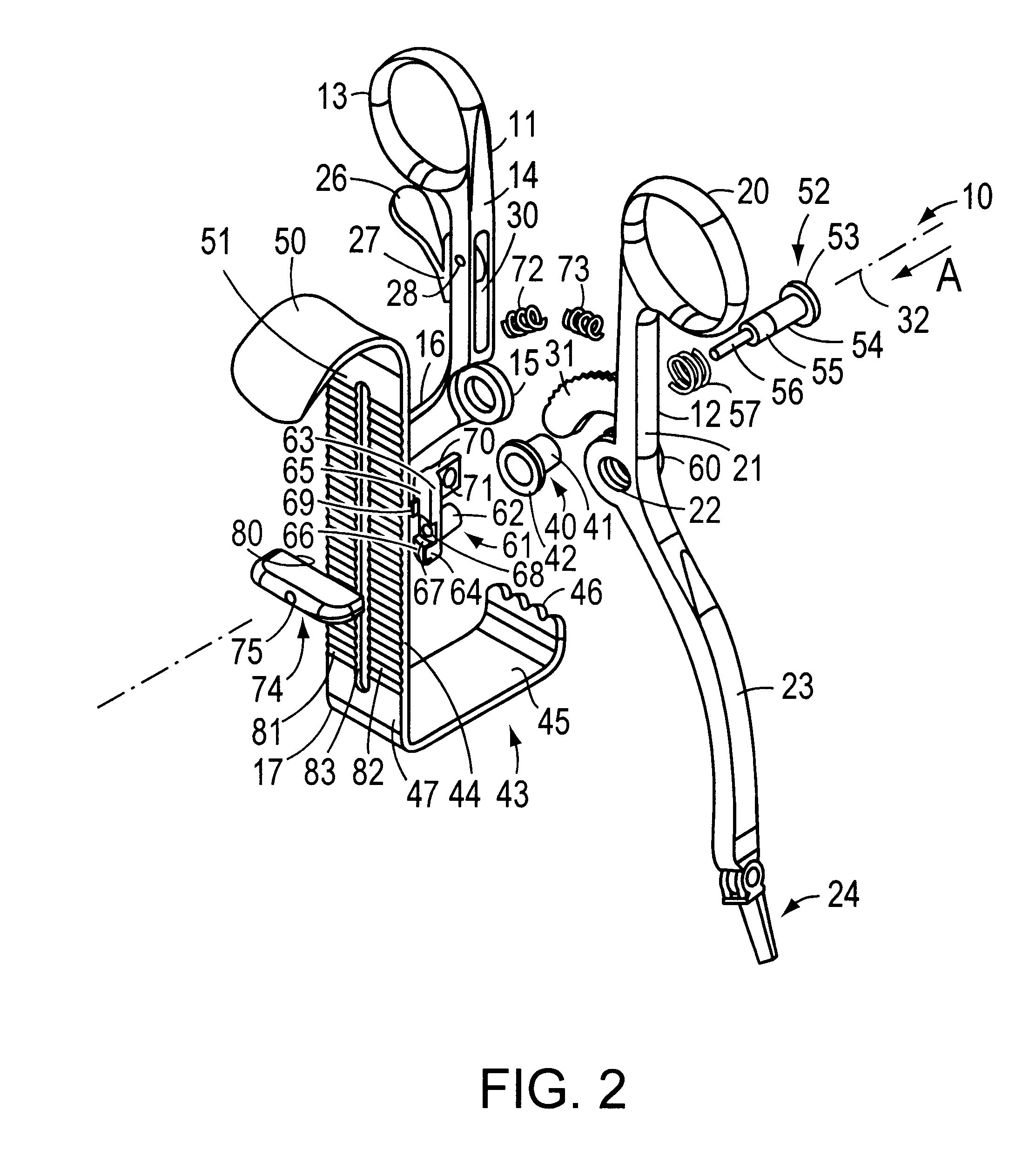
Looking first at arm 11 as depicted in FIGS. 1 and 2, a finger grip 13 at a first end provides a grip for a surgeon. An upper portion 14 extends between the finger grip 13 and an intermediate portion constituted by a flat member 15 having a generally annular form. A lower portion 16 extends from the intermediate portion 15 to a hinged claw coupler 17 that receives a claw 18. Likewise the second arm 12 includes a finger grip 20, an upper portion 21, an intermediate portion 22, a lower portion 23 and a hinged claw coupler 24 that also receives a claw 25, like the claw 18. In this case, however, the intermediate portion 22 is formed by two annular members spaced by an amount corresponding to the thickness of the intermediate portion 15.

As particularly shown in FIG. 2, the first arm 11...


PUM


Abstract

A tissue retractor with an adjustable center claw. The retractor includes two pivoted retractor arms. An axially and angularly displaceable, spring biased clamping mechanism is positioned on the pivot axis. In a mounting position, a elongated clamping element aligns with a slot in the center claw. When the center claw is positioned and the clamp moves to its clamping position, the elongated clamping member clamps the center claw in position. The counterfacing surfaces of the center claw and the clamping member are toothed to provide a positive one-way ratchet clamp.

Description

1. Field of the InventionThis invention generally relates to surgical instruments and more specifically to tissue retractors for use in various surgical procedures.2. Description of Related ArtSurgical retractors are well known in the medical arts, particularly retractors that separate body tissue to enable a surgeon access to an operating site. Generally these retractors include two arms that can pivot about an axis at an intermediate position to form a scissors-like mechanism. Squeezing finger grips at one end of each arm causes a pair of retractor claws at the other ends of each arm to separate. Once the desired tissue separation is achieved, a ratchet sector on one arm and a pawl on the other arm lock the arms in place relative to each other and thereby maintain the tissue separation. The following patents disclose some examples of such retractors:U.S. Pat. No. 3,038,467 (1962) SovatkinU.S. Pat. No. 3,470,872 (1969) GrieshaberThese retractors, however, only provide separation at...

Claims


Application Information

Patent Timeline
IPC IPC(8): A61B17/02
CPCA61B17/0206
Inventor BESTER, LEON W.WALSH, DAVID A.
Owner LAB ENG & MFG
Why Eureka
Try Eureka