Electric saw communication

a technology of electric saws and communication channels, applied in the field of electric saws, can solve the problems of comparatively heavy hydraulic wall saws and difficult setup, and achieve the effect of convenient handling and convenient electric saw handling

Active Publication Date: 2016-05-03
HUSQVARNA AB
View PDF32 Cites 18 Cited by
  • Summary
  • Abstract
  • Description
  • Claims
  • Application Information

AI Technical Summary

Benefits of technology

[0006]It is an object of the invention to provide an electric saw being portable and / or wheeled, such as a wall saw or a floor saw comprising a circular rotatable saw blade and a drive motor, which electric saw can easily be handled. This object is achieved by an electric saw being powered by an external power supply through a multicore cable that also includes communication wires for data communication between the electric saw and the power supply. An electric saw using an external power supply where the power supply and communication wires are in one single multicore cable makes the handling of the electric saw easier, since less cables needs to be used.
[0012]Another object of the invention is to provide a three phase electrical motor with Hall Effect sensors that can be easily adjusted in position. This object is achieved by providing a three phase electrical motor having an inner stator and an outer rotor comprising a plurality of permanent magnets with at least three Hall Effect sensors mounted around the periphery of the outer rotor for determining the electrical position and / or electrical positional change by monitoring the leak magnetic flux of the permanent magnets. By having the Hall Effect sensors mounted around the periphery the Hall Effect sensors can easily be accessed for adjusting their position.
[0013]Preferably the Hall Effect sensors are mounted on a common ring shaped circuit board, each Hall Effect sensor mounted at predetermined angular positions. Preferably, the ring shaped circuit board can at least to some extent be rotably adjusted. By mounting the Hall Effect sensors on a ring shaped circuit board their position in relation to the stator can be easily adjusted while maintaining their mutual position.
[0025]Preferably each packet includes a redundancy or checksum code corresponding to the information code for reducing the risk of information losses.

Problems solved by technology

However, hydraulic wall saws are comparatively heavy and not easy to set up, and comparatively low-weight electric wall saws, such as the one disclosed in US 2006 / 0189258 A1, for example, have been introduced on the market.

Method used


Image

  • Electric saw communication
  • Electric saw communication
  • Electric saw communication

Examples


Embodiment Construction

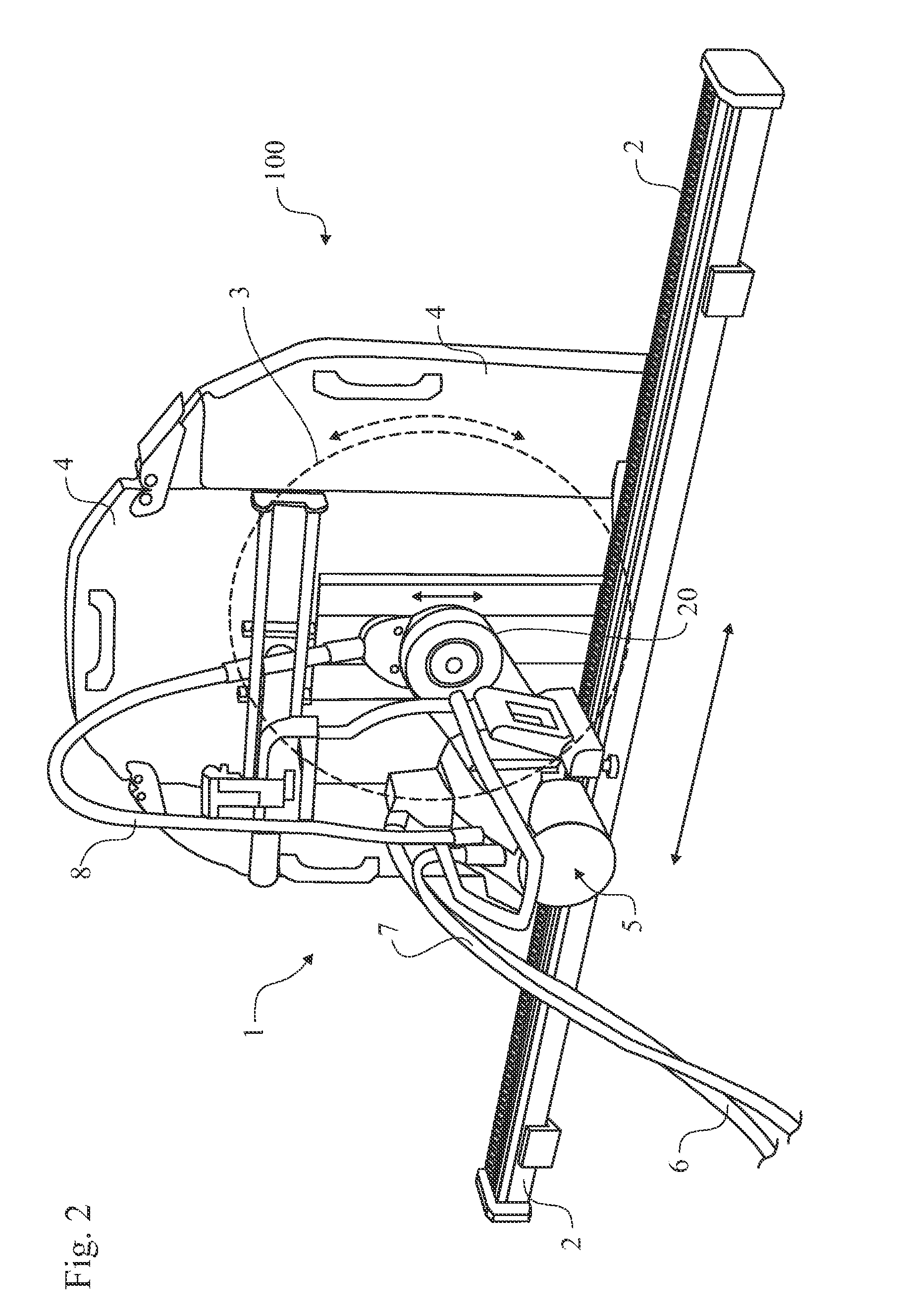
[0041]Broadly, the present invention relates to a construction machine having a prime mover, a rotatable tool driven by the prime mover, and a transmission for interconnecting an output shaft of the prime mover to the rotatable tool in order to transform an unsuitable high speed and low torque of the prime mover output shaft to a more useable lower speed with higher torque at the rotatable tool. An exemplary embodiment of such a construction machine is a wall saw having a motor, a circular saw blade driven by the motor, and a transmission for interconnecting an output shaft of the motor to the rotatable saw blade. In spite of its name, a wall saw might as well be used for sawing through a floor or a ceiling.

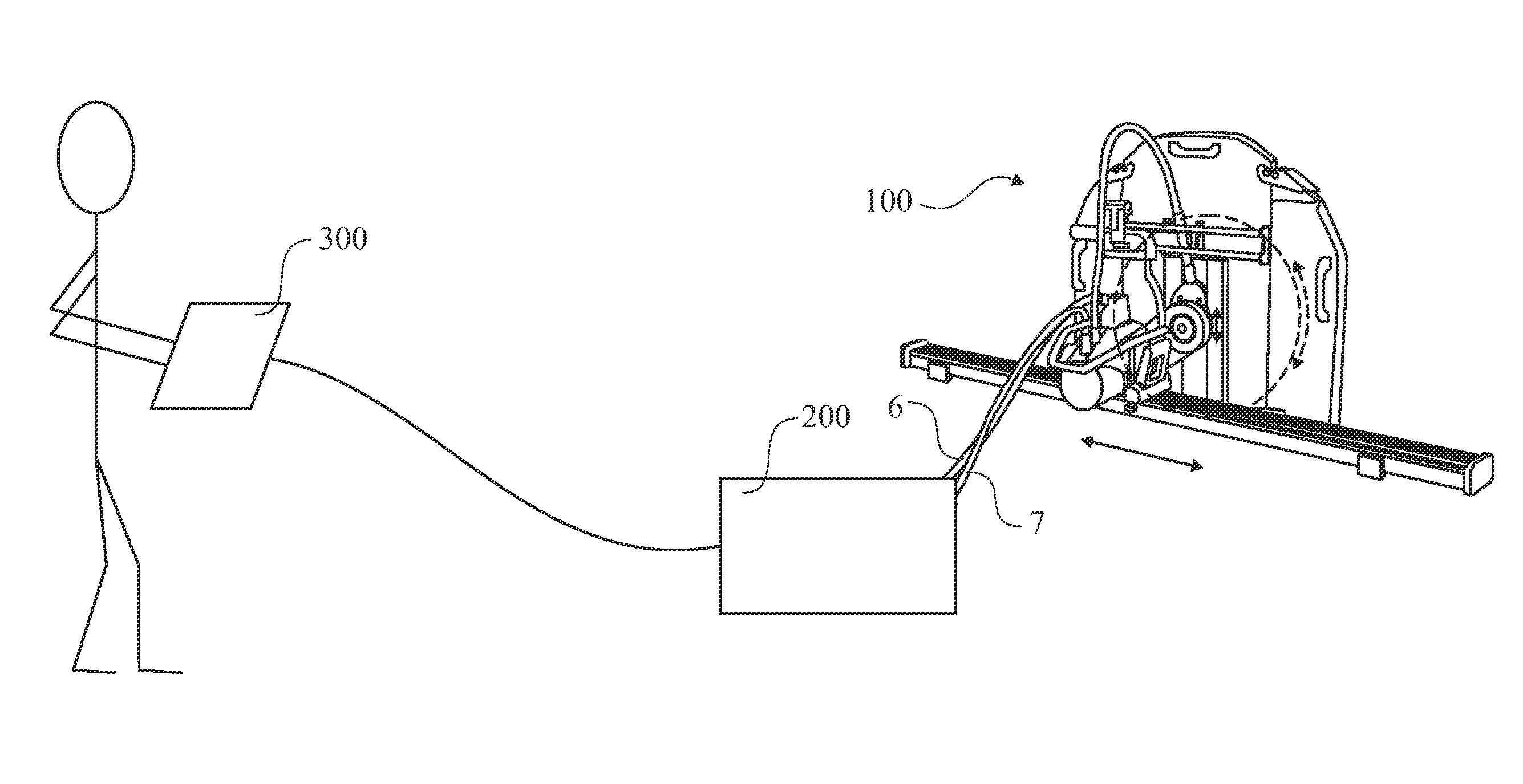
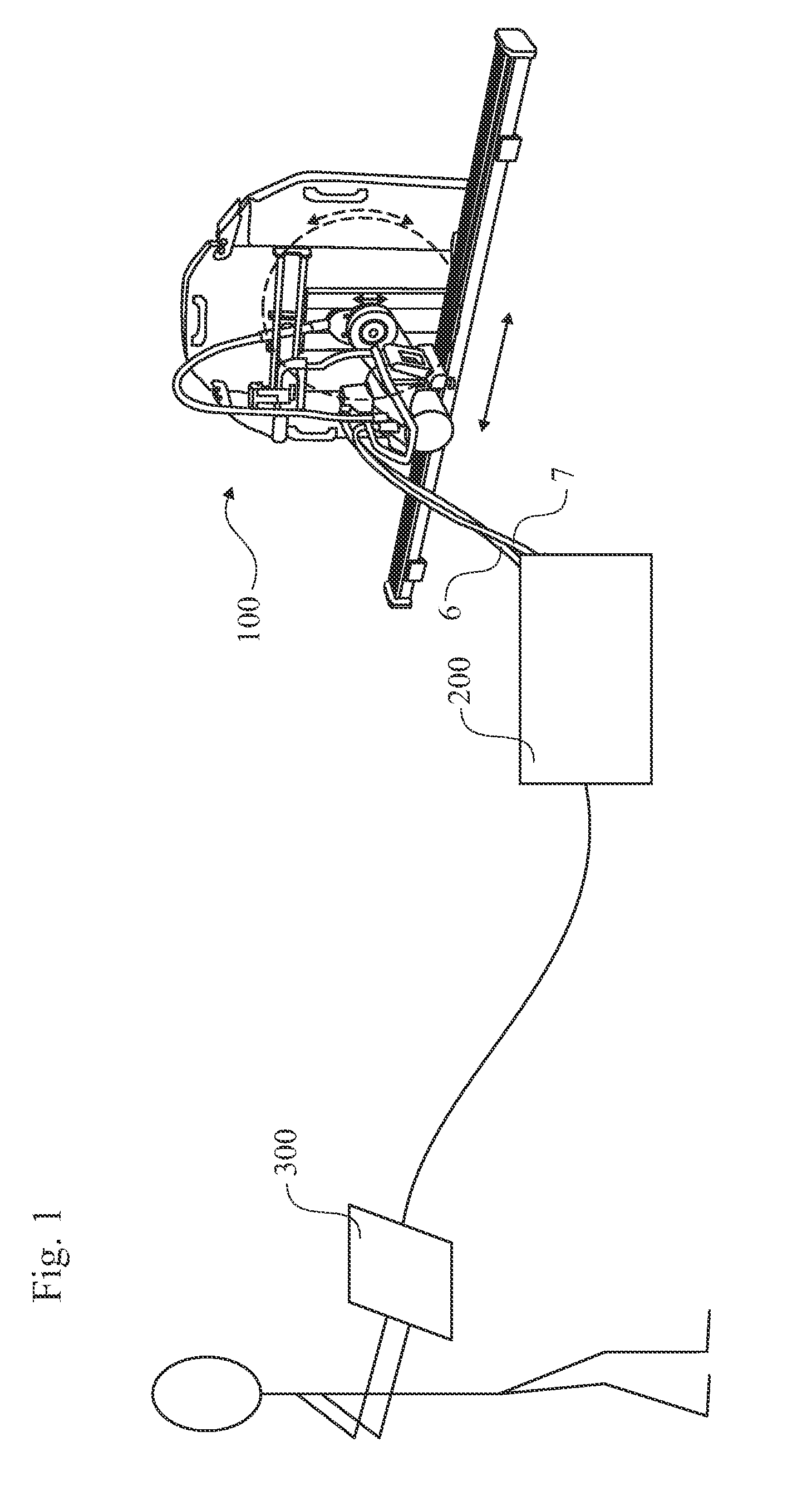
[0042]FIG. 1 is an overview of a wall saw system, including a wall saw assembly 100, an external power supply 200, and a remote control unit 300. The power supply 200 supplies power through a cable 6 to the wall saw assembly 100, and also receives feedback data from the wall saw ...


PUM

PropertyMeasurementUnit
timeaaaaaaaaaa
poweraaaaaaaaaa
leak magnetic fluxaaaaaaaaaa

Abstract

Electric saw being powered by an external power supply through a multicore cable. The multicore cable includes electrical wires for supplying power to the motors of the electric saw and communication wires for data communication between the electric saw and the power supply. Two motors of the electric saw are three phase permanent magnet motors, with an outer rotor and an inner stator. Each of the two motors has three Hall Effect sensors located around the outer rotor.

Description

TECHNICAL FIELD[0001]The present invention relates to electrical saws, such as portable wall saws or wheeled floor saws, with external power supplies, more particular an electrical motor thereof, a method for communicating information from the electric saw to the power supply, a communication protocol facilitating communication between the power supply and the electric saw.BACKGROUND ART[0002]Construction machinery is used in renovating, reconstructing and extending buildings, for example. Wall saws are used for cutting and extending openings for doors, windows and light wells, etc., corrective work on facades, partition walls and garden walls, etc., and controlled demolition of concrete. Wall saws and similar construction machinery have a prime mover, such as a motor, and a rotary tool driven by the motor.[0003]A wall saw usually includes a rack, i.e. a toothed bar or rod, intended to be attached to and equidistantly spaced from the wall, which is to be sawed through. A carriage ca...

Claims


Application Information

Patent Timeline
Patent Type & Authority Patents(United States)
IPC IPC(8): B25F5/00H02K11/00B28D1/04H02K29/08B23D47/08B23D47/12B23D59/00H02P5/74H02P6/04H02P6/16
CPCB28D1/045B23D47/08B23D47/12B23D59/002B28D1/044H02P5/74H02P6/04H02P6/16
Inventor JONSSON, ANDREASLUNDGREN, MAGNUSBERGVALL, BENGT-ALLAN
Owner HUSQVARNA AB
Why Eureka
Try Eureka