

Beam hanger, building framework structure and installation method
A technology of frame structure and hanging parts, which is applied in the construction of buildings, construction, and the processing of building materials, etc., can solve the problems of reducing installation efficiency, improving installation difficulty, and many connection links, etc., to achieve improved utilization and aesthetics, Reduce the effect of excessive stress concentration and easy position adjustment
- Summary
- Abstract
- Description
- Claims
- Application Information
AI Technical Summary
Problems solved by technology
Method used
Image

Examples
Embodiment 1
[0050] Example 1
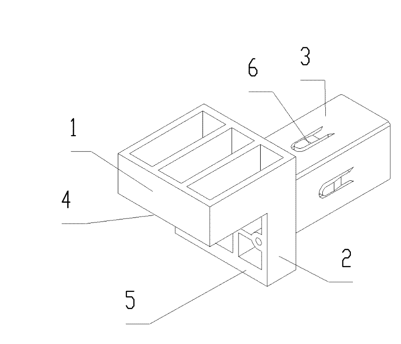
[0051] Such as figure 1 As shown, a beam hanger is a casting, including a block-shaped suspension part 1 supported on the beam, and a block-shaped connection part 2 extending downward from the bottom surface 4 of the vertical suspension part 1. On the side of the connection part 2 facing away from the suspension part 1, a square tube-shaped beam plug joint 3 is inserted into the beam end so as to be plugged with the beam end. The bottom surface 4 of the suspension part is the first supported surface directly supported on the beam; the vertical side 5 connected to the bottom surface 4 on the connecting part is the beam side resisting surface resisted by the beam, and the beam side resisting surface is located on the first supported surface below. Elastic tongues 6 are arranged on four sides of the beam plug joint 3 , the end of the elastic tongue 6 away from the connecting portion 2 is connected to the beam plug joint 3 , and the end of the elastic tongue 6 f...
Embodiment 2
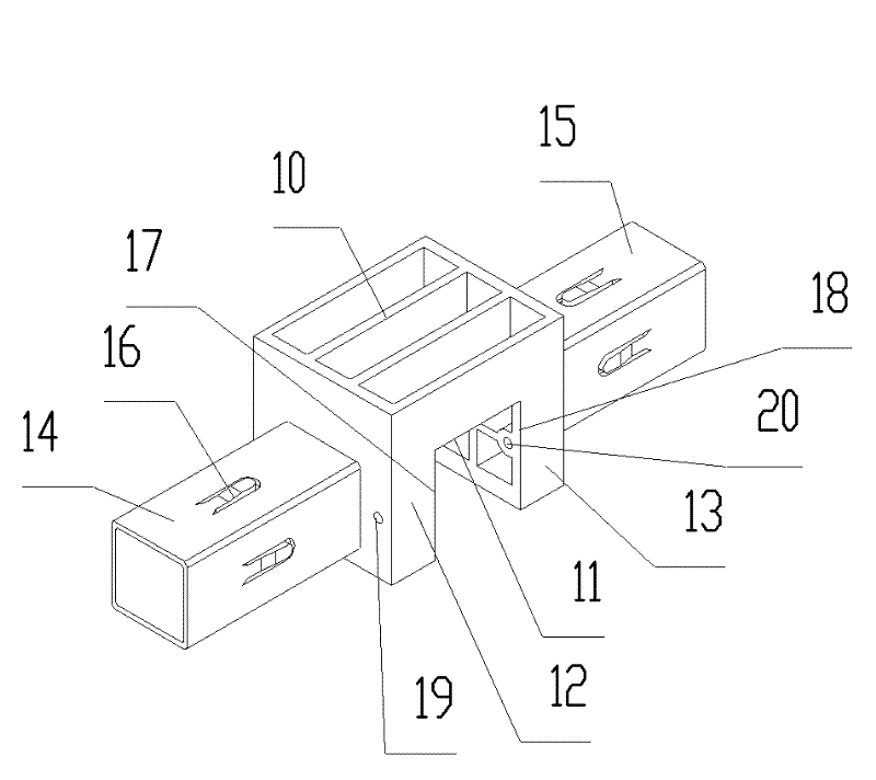
[0053] Such as figure 2 As shown, a beam hanger includes a suspension part 10 supported on the beam, a symmetrical block-shaped first connecting part 12 and a block-shaped first connecting part 12 extending vertically downward from the bottom surface 11 of the suspension part 10. Two connecting parts 13 are arranged on the side of the first connecting part 12 away from the suspension part 10, inserted into the beam end so as to insert a first beam plug joint 14 with the beam end, arranged on the second side of the suspension part 10 away from On the side of the connecting part 13, a second beam plug-in joint 15 is inserted into another beam end so as to be inserted into the beam end. The structure of the second beam plug joint 15 is the same as that of the first beam plug joint, and the first beam plug joint 14 and the second beam plug joint 15 are symmetrical about the vertical plane at their central positions.
[0054] Elastic tongues 16 are provided on the four sides of t...
Embodiment 3
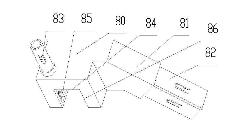
[0058] Such as image 3 As shown, a beam hanger includes a suspension part 80 supported on the beam, a connection part 81 extending vertically from one side of the suspension part 80 to one side and then bent downwards, and is arranged on the connection part 81 on the end face facing downwards, inserted into the end of the beam so as to insert the beam plug joint 82 with the end of the beam, and set on the top surface of the suspension part 80 to be inserted into the vertical support column of the handrail. Insert the connector 83 vertically. The structure of the beam plug joint 82 is the same as that of the beam plug joint of the first embodiment.
[0059] The bottom of the hanging part is provided with a U-shaped through groove with three faces perpendicular to each other. The bottom surface 84 of the U-shaped through groove is the first supported surface directly supported on the beam; the side 85 of the U-shaped through groove It is the first beam side resisting surface ...
PUM
 Abstract
Description
Claims
Application Information