
Graft fixation device

a technology of graft and fixation device, which is applied in the direction of surgical staples, ligaments, prostheses, etc., can solve the problems of significant patient morbidity, difficult use of many of these devices in a minimally invasive arthroscopic procedure, and surgical challeng

Inactive Publication Date: 2007-05-08
DEPUY SYNTHES PROD INC
View PDF38 Cites 322 Cited by
  • Summary
  • Abstract
  • Description
  • Claims
  • Application Information

AI Technical Summary

Benefits of technology

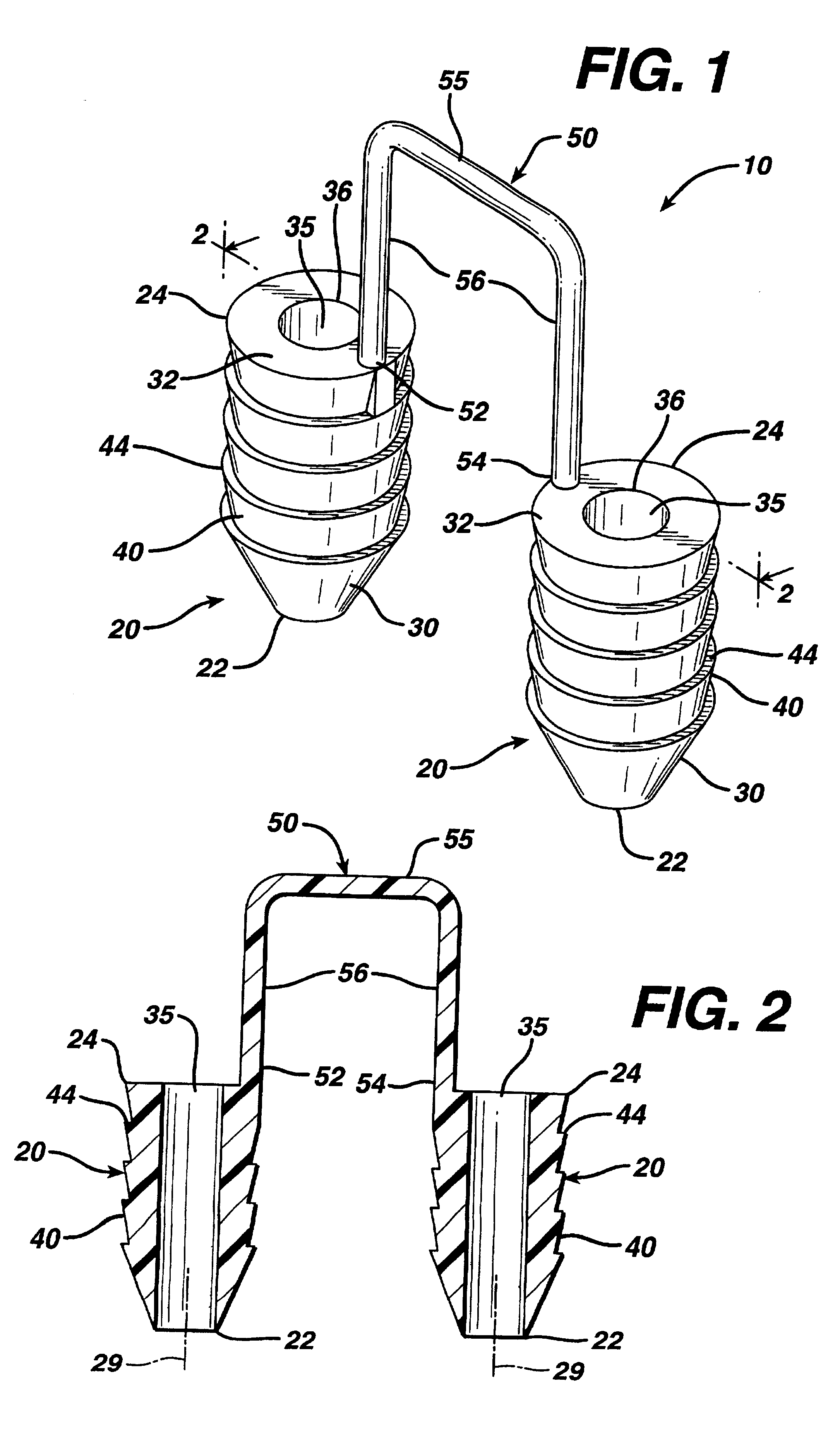
[0007]Therefore, it is an object of the present invention to provide a fixation device that effectively fixates a tissue-engineered matrix to a bone or other anchoring site, thereby enabling the implanted matrix to remain in place while the tissue continues to grow and regenerate.
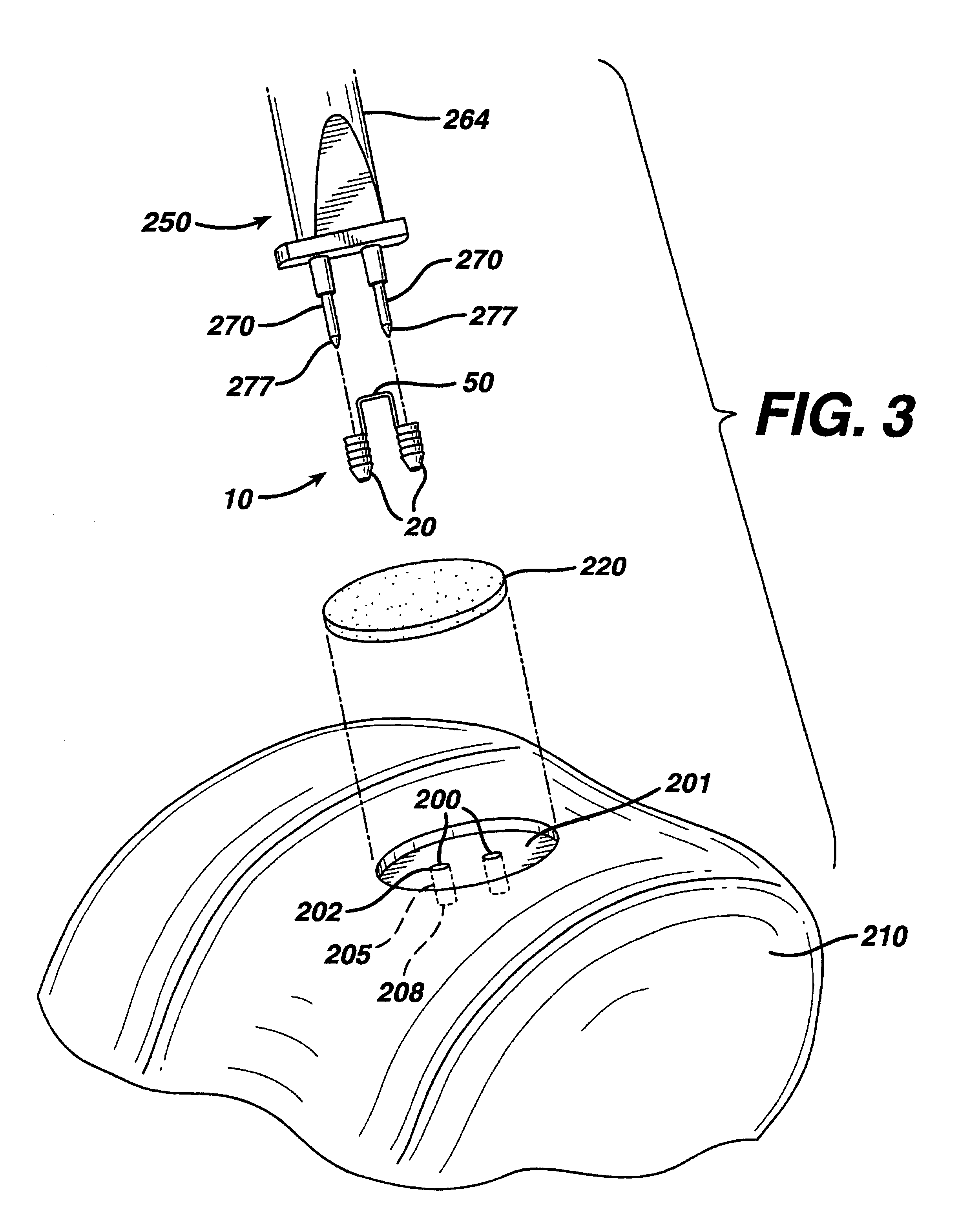
[0008]It is a further object of the present invention to provide such a device for fixating a matrix to a bone site which is easily installed using an arthroscopic procedure or an open procedure.
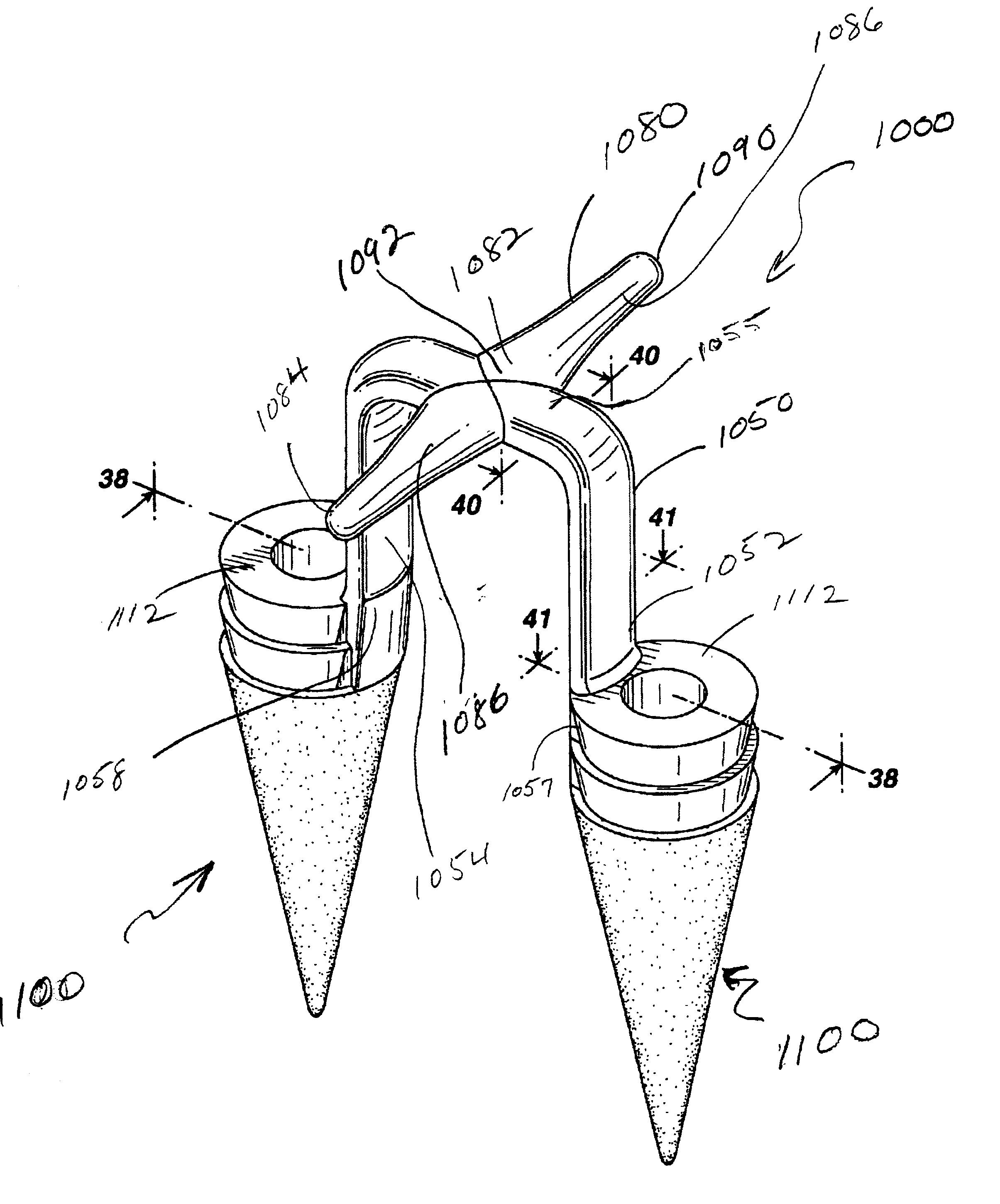
[0011]Accordingly, a graft fixation device is disclosed. The graft fixation device has first and second implantation members. The members are elongated and preferably have a cylindrical configuration. The members also have distal ends, proximal ends, and longitudinal axes. There are longitudinal passages extending through the entire length of each implantation member. The members have outer surfaces. The implantation members are connected to each other by a rod member having first and second ends and a central section. The first end of the rod member extends from the proximal end of the first implantation member and the second end of the rod member extends from the proximal end of the second implantation member. The rod member is preferably relatively rigid and may be configured to have a variety of geometric shapes, for example, an inverted “U” shape. However, the rod member may also be flexible. The rod member maintains the implantation members at a relatively fixed distance from each other. The central section of the rod member is designed to engage a section of a tissue-engineered matrix implant. In a preferred embodiment, the implantation members have a series of ridges extending out from the outer surfaces of the implantation members to assist in preventing withdrawal from a bone site or other anchoring site after the implantation members are implanted into previously-created bore holes.
[0014]Yet another aspect of the present invention is a graft fixation device. The graft fixation device has first and second implantation members. The members are elongated and preferably have a cylindrical configuration. The members also have distal ends, proximal ends, and longitudinal axes. There are longitudinal passages extending through the entire length of each implantation member. The members have outer surfaces. The implantation members are connected to each other by a rod member having first and second ends and a central section. The first end of the rod member extends from the proximal end of the first implantation member and the second end of the rod member extends from the proximal end of the second implantation member. The rod member is preferably relatively rigid and may be configured to have a variety of geometric shapes, for example, an inverted “U” shape. However, the rod member may also be flexible. The rod member maintains the b The wing member facilitates such engagement. In a preferred embodiment, the implantation members have a series of ridges extending out from the outer surfaces of the implantation members to assist in preventing withdrawal from a bone site or other anchoring site after the implantation members are implanted into previously-created bore holes.

Problems solved by technology

Although existing matrix fixation devices are adequate for their intended use, there are also some disadvantages attendant with their use.
Other disadvantages include the difficulty in using many of these devices in a minimally invasive arthroscopic procedure.
Additional disadvantages include the difficulty and surgical challenge of harvesting a piece of periosteum for use as a periosteal flap, the significant patient morbidity associated with such harvesting, and the difficulty in suturing such a thin, compliant material to surrounding tissue.

Method used


Image

  • Graft fixation device
  • Graft fixation device
  • Graft fixation device

Examples


example

[0072]Six sheep were prepared for a surgical procedure using standard aseptic surgical techniques including the use of fully sterilized instruments and equipment, and conventional anesthesia procedures and protocols. The surgeon then created 7 mm diameter chondral (full thickness cartilage) defects on a weight-bearing area of the medial femoral condyle and in the trochlear groove in the right stifle (knee) in each of the six skeletally mature sheep. Defects were created using a specialized drill with a depth-stop to prevent subchondral bone exposure or penetration. The base surfaces of all the defects were then microfractured with a specialized micropick tool to provide access for cellular migration. The subjects were then separated into three groups of two subjects each:[0073]Group 1: defect filled with a collagen matrix, fixed with the graft fixation device of the present invention.[0074]Group 2: defect filled with a collagen matrix, fixed with 9-0 absorbable Vicryl™ suture (inter...


PUM


Abstract

A graft fixation device combination. The device is useful for affixing a tissue graft to a bone or other body surface. The fixation device has two implantation members connected by a graft retention member. The retention member optionally has at least one lateral wing member extending therefrom. The implantation members have longitudinal passageways therethrough. The graft fixation device also has an insertion member extending from the distal end of each implantation member, the insertion member having a longitudinal passage having a distal blind wall. The passages of the implantation members and the insertion members are in communication with each other, and may be mounted onto insertion members.

Description

[0001]This is a Continuation-In-Part application of commonly assigned co-pending U.S. patent application Ser. No. 09 / 793,036 filed on Feb. 26, 2001 now U.S. Pat. No. 6,402,766 which is a Continuation-In-Part application of commonly-assigned, copending U.S. patent application Ser. No. 09 / 535,183 filed on Mar. 27, 2000 which is a Continuation-In-Part of commonly-assigned, copending patent application U.S. patent application Ser. No. 09 / 360,367 filed on Jul. 23, 1999 now U.S. Pat. No. 6,179,840, which are incorporated by reference.TECHNICAL FIELD[0002]The field of art to which this invention relates is surgical fastening devices, in particular, surgical fastening devices for fixating tissue grafts to bone.BACKGROUND OF THE INVENTION[0003]The medical technology associated with tissue engineering has advanced at a rapid pace. In particular, it is now known to harvest cells from the human body, for example, chondrocytes and fibrochrondrocytes from the knee joint. These autologous cells ar...

Claims


Application Information

Patent Timeline
IPC IPC(8): A61B17/08A61B17/00A61B17/56A61B17/04A61B17/064A61B17/068A61B17/92A61F2/08A61F2/28
CPCA61B17/0401A61B17/0642A61B17/068A61B17/00234A61B17/06A61B17/064A61B17/92A61B2017/00004A61B2017/00243A61B2017/00783A61B2017/0406A61B2017/0409A61B2017/0412A61B2017/0414A61B2017/0419A61B2017/0427A61B2017/0445A61B2017/06057A61B2017/0608A61B2017/0646A61B2017/0647A61F2/0063A61F2/0811A61F2/2846
Inventor BOWMAN, STEVEN M.JUSTIN, DANIEL F.TENHUISEN, KEVOR SHANEJANAS, VICTOR F.CAULDWELL, NATHAN S.
Owner DEPUY SYNTHES PROD INC
Learn More