Electric, telephone or network access control system and method

a technology for access control and telephones, applied in the direction of programme control, process and machine control, coupling device connections, etc., can solve the problems of not having the unique capability of preventing an individual, damage to the telephone or network, and no device that will conveniently control the access of other phone or network receptacles, etc., to achieve the effect of convenient attachment or incorporation of an electric devi

Inactive Publication Date: 2007-01-23
POURCHOT SHAWN C
View PDF13 Cites 342 Cited by
  • Summary
  • Abstract
  • Description
  • Claims
  • Application Information

AI Technical Summary

Benefits of technology

[0046]An additional object of this invention is to create a method to control the time that receptacles are in use.
[0048]Still another object of this invention is to create an electric, telephone or network control system that can easily be installed in existing receptacles and plugs or be incorporated within new receptacles and plugs.
[0049]A final object of this invention is to create a simple and inexpensive system and method to control electric, telephone and network receptacles.

Problems solved by technology

Various cumbersome arrangements have been proposed in the past for preventing children from harm in the event they insert foreign objects into electrical receptacles.
However, to date, there have not been any devices that will control the access for other phone or network receptacles conveniently.
However, they are configured to only provide power or data to those who have purchased the correct transponder tags to activate the respective receptacle being tapped.
Plugging the telephone into a data port or vice versa may cause damage to the telephone or network.
The protector may be easily applied without disturbing the electrical wiring but can only be removed by the unscrewing of the plate retention screw using a screwdriver.
This patent describes a control system for remotely switching on and off electrical appliances but does not offer the unique capability of preventing an individual from inserting the wrong plug into a receptacle or for preventing unauthorized individuals from using specific receptacles.
This patent describes a highly sophisticated expensive system for providing different services throughout a house but does not offer the unique inexpensive system disclosed within this patent that can be a retrofit to one or more receptacles within a house or office.
This patent describes a sophisticated system designed for the implementation into hotels and the like for improved control and supervision in the maintenance of the facility but does not offer the capability of controlled access of the electric, telephone or network receptacles in the rooms for the possibility of increased revenues.
This patent describes another child proof cover for an electrical receptacle but does not offer the capability of ceasing the current to flow to the receptacle unless the proper plug is inserted with a transponder identification RFID tag outlined within this patent.
This patent describes another sophisticated electronic method of controlling the appliances within a house but will not keep individuals from putting the wrong plug into a receptacle.
This patent describes a cumbersome safety cover box for electrical outlets but does not control the current from the receptacle and would be extremely awkward to install on all of the outlet receptacles of a house.
This patent describes another cumbersome safety cover box for electrical outlets but does not control the current from the receptacle and would be extremely awkward to install on all of the outlet receptacles of a house.
This patent describes an exterior weatherproof electrical enclosure with a timer to turn on and off Christmas and security lighting but does not offer any practical protection for phone or network receptacles.
Such system deters theft of the articles.
Although this patent uses the RFID technology, it involves the incorporation of this invention into manufactured appliances and could not be simply attached to the plugs of the appliance and would not work effectively on telephone or network access receptacles.

Method used


Image

  • Electric, telephone or network access control system and method
  • Electric, telephone or network access control system and method
  • Electric, telephone or network access control system and method

Examples


Embodiment Construction

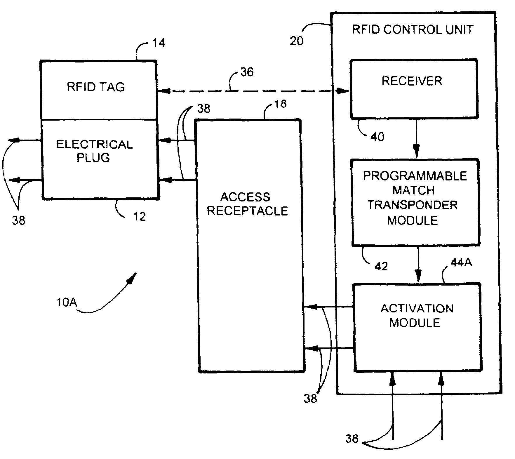
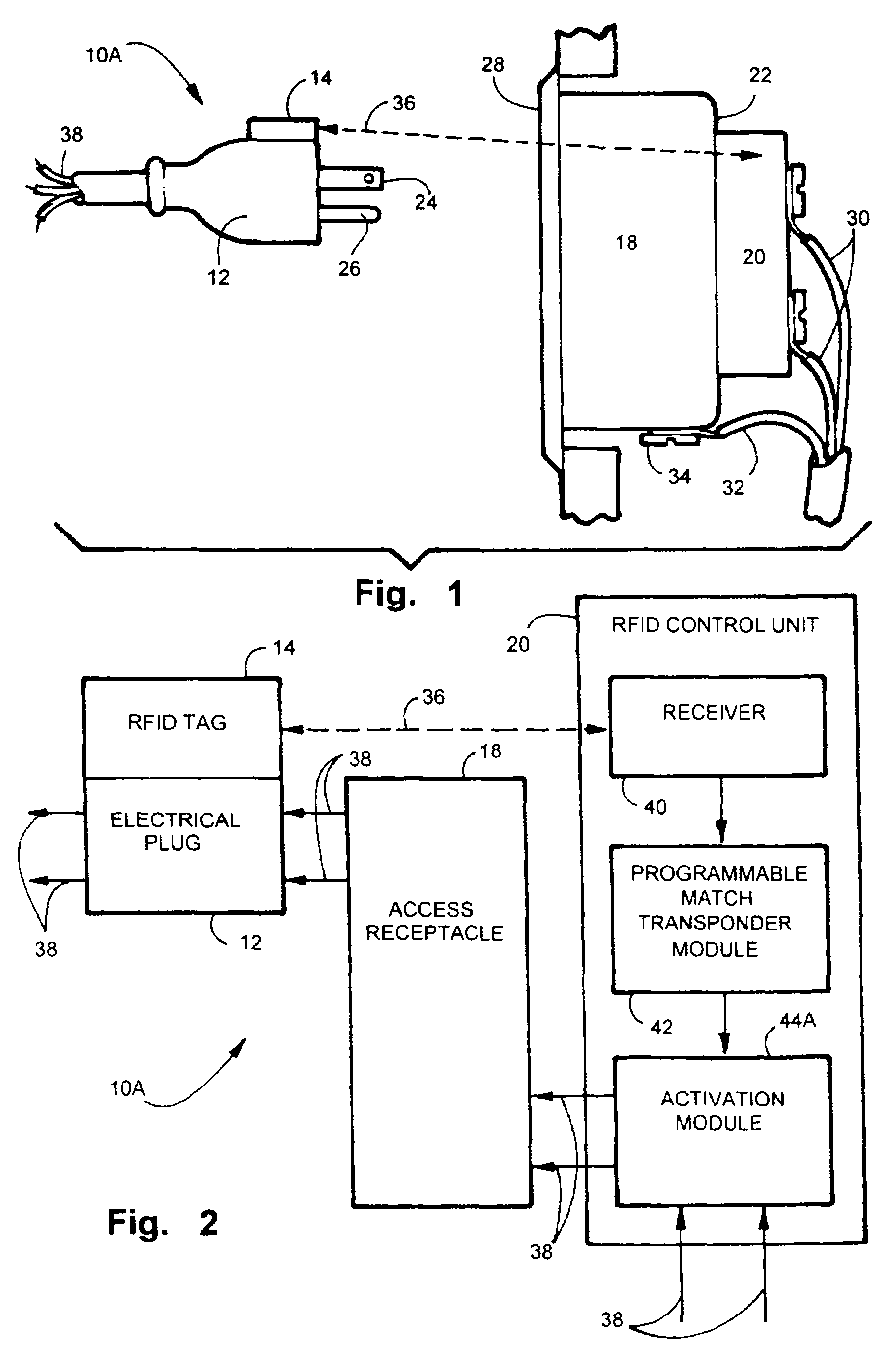
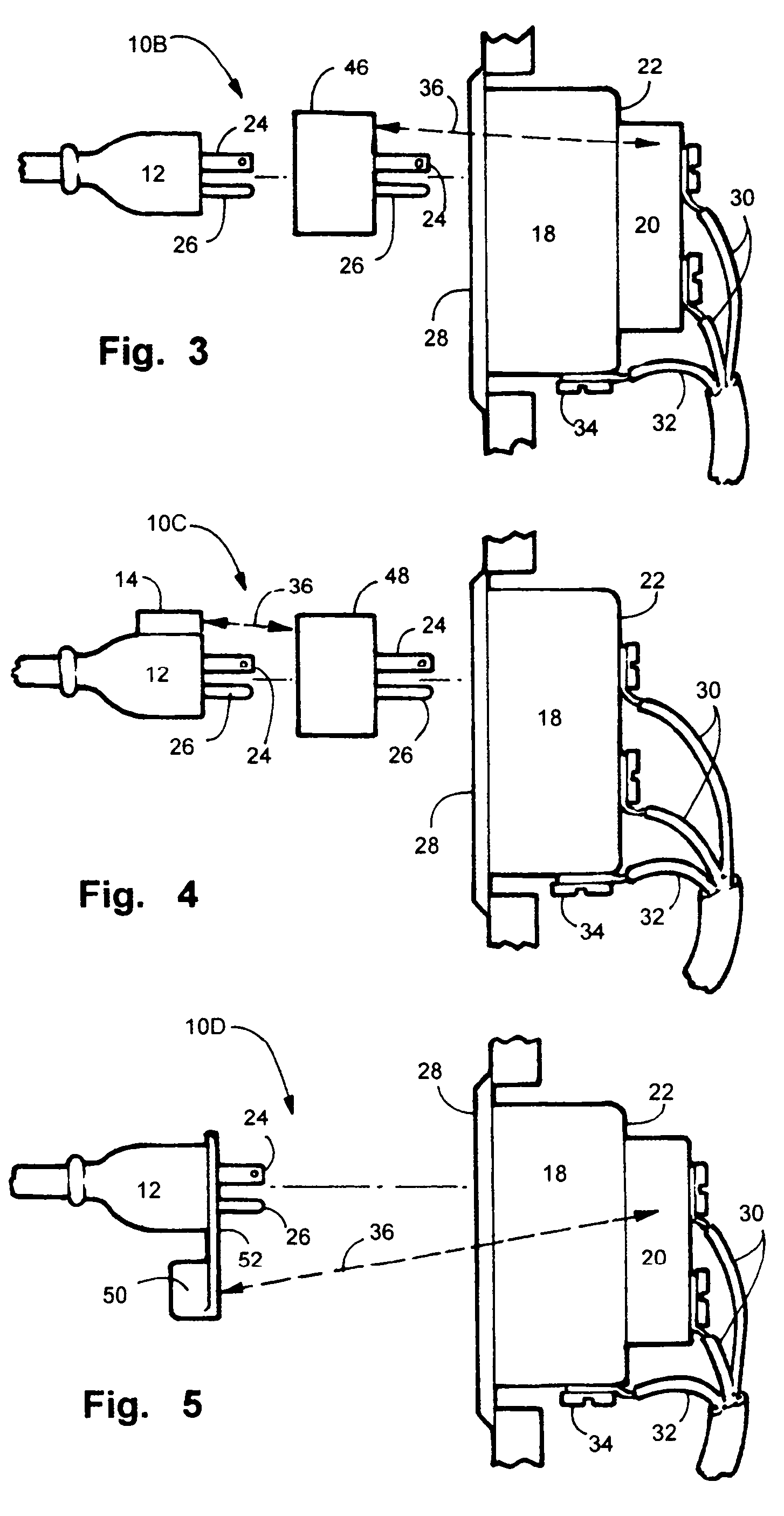
[0059]Referring now to the drawings, wherein similar parts of the invention are identified by like reference numerals, there is seen in FIG. 1 the electric, telephone or network access control system and method 10A shown as a side elevation of the preferred embodiment with a conventional electrical plug 12 having a RFID tag 14 mounted on the top surface 16 or attached to the cord using other means of attachment. In use, to activate electrical communication, the RFID tag 14 engaged on the distal end of the wire or cord is placed adjacent to a conventional electrical access receptacle body 18 with a RFID control unit 20 mounted on the back side 22. It must be understood at this time that the illustration shows a conventional AC plug 12 and AC receptacle body 18, but the unique features of this invention enable the device and method to be incorporated into a wide variety of plugs and receptacles including those of the telephone and the Ethernet network such as conventional category fiv...


PUM


Abstract

An apparatus and method for controlling user access to electrical receptacles and telephone and network communications receptacles. The device features a short range radio receiver and one or a plurality of RF energized radio identification tags with transmittable identification transponder codes. The receptacle contains circuitry that detects the immediate presence of energized transponders with proper identification codes and only enables the electric, telephone or network access from the receptacle to become active if the correct matching transponder identification code is present. The tag is a small flexible device having one side that may be attached to the plug or the receptacle or interfaced therebetween. Access to the power or network is allowed for a defined duration of time or only so long as the transponder remains energized and transmits the identification code.

Description

FIELD OF THE INVENTION[0001]The disclosed device relates to the field of the provision of a controlled access to a variety of electric, telephone and network receptacles providing utility or communication services. More particularly, it relates to control to access of such services through the use of radio frequency identification technology (RFID) in combination with switching technology. Access to most energy providing systems and communication providers is generally provided through common receptacles of all kinds offering open access to anyone who wishes to insert a matching plug into a properly configured receptacle. Further, in the case of small children inserting foreign objects into such receptacles, such unpredictable behavior can result in serious injury to them or damage to a system. The disclosed device herein provides a new and unique apparatus and method for precisely controlling the access to a wide variety of receptacles in many varied locations.BACKGROUND OF THE INV...

Claims


Application Information

Patent Timeline
Patent Type & Authority Patents(United States)
IPC IPC(8): G05B19/00H01R13/44H01R13/703H04M1/02H04M1/67H04Q1/00
CPCH04M1/67H04M1/0293H01R13/7038H01R13/44
Inventor POURCHOT, SHAWN C.
Owner POURCHOT SHAWN C
Why Eureka
Try Eureka