Eureka AIR delivers breakthrough ideas for toughest innovation challenges, trusted by R&D personnel around the world.

Gangable cable support with improved stiffness

a cable support and stiffness technology, applied in the field of cable supports, can solve the problems of not providing a balanced support and evenly distributed weight, affecting the service life of the cable, so as to improve the stiffness of the support and improve the withstanding of bending moments

Active Publication Date: 2008-08-05
ARLINGTON INDS
View PDF6 Cites 40 Cited by
  • Summary
  • Abstract
  • Description
  • Claims
  • Application Information

AI Technical Summary

Benefits of technology

[0010]Accordingly, the cable support of the present invention exhibits several advantages over prior art cable supports for communications cables. The cable support is of a design that insures a suspended weight will be balanced evenly below the anchoring point. The cable support includes stiffeners for improving the stiffness of the support to allow improved withstanding of bending moments caused by the suspended weight of cable bundles. The cable support also includes a cable retaining arrangement for keeping cable bundles secured within the support.
[0011]Additionally, the present invention provides a cable support that may easily be ganged directly to additional like cable supports without use of a separate bracket or other piece. This simplifies the task of ganging cable supports and thereby eliminates the need to stock additional parts such as brackets.
[0012]When ganged together, the present invention also has the advantage of presenting a balanced column of cable supports. The cable supports link to each other in a manner in which the weight is distributed evenly from the bottommost support to the topmost support. This has the advantage of causing less undue stress to individual portions of the combined tree of supports.
[0014]The invention is a one-piece cable support having a box-shaped mounting assembly. The box-shaped mounting assembly extends over a cable tray portion of the cable support and includes several optional mounting apertures. Once secured to a building structure through the box-shaped assembly, the weight of a suspended bundle of cables is distributed evenly below the box-shaped assembly, thereby permitting the load to be balanced evenly below the assembly and reducing the bending moment and therefore the stress on the wall portion connecting the cable tray and mounting assembly portions of the support. A bracket assembly is provided on the bottom of the cable support to allow easy ganging of multiple cable supports without the need for specialized brackets. Stiffeners are included on the cable support to improve the withstanding of bending forces. A cable retaining arrangement secures cable bundles within the support.

Problems solved by technology

Great care is necessary when running UTP cable, as any kinking, sharp bends, or damage to the cable can cause undesirable side effects, such as creation of cross-talk or static between the various conductors.
However, routing cable throughout an existing building presents many problems.
Although the prior art J-hooks provide a secure anchor for communications cables, they do not provide a balanced support and evenly distribute the weight of a suspended bundle of cables on the top stem.
Therefore, a bundle of cables suspended in a J-hook may eventually cause the hook material to fatigue and break near the anchoring point, especially when anchored to structures that are susceptible to vibrations, such as air plenums and the like.
The prior art J-hooks are also less than optimal when used to support several separate bundles of cables from the same anchoring point.

Method used


Image

  • Gangable cable support with improved stiffness
  • Gangable cable support with improved stiffness
  • Gangable cable support with improved stiffness

Examples


Embodiment Construction

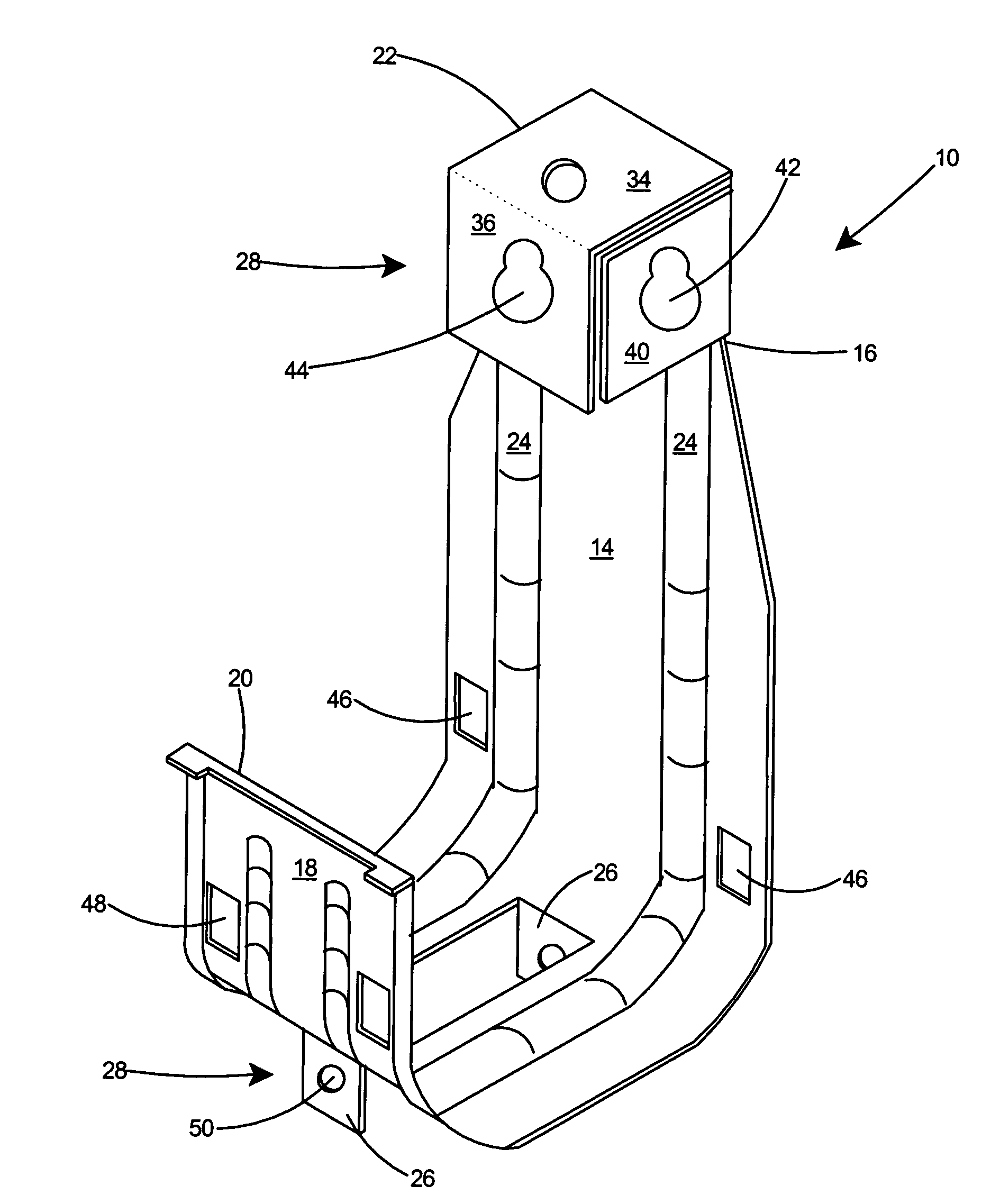
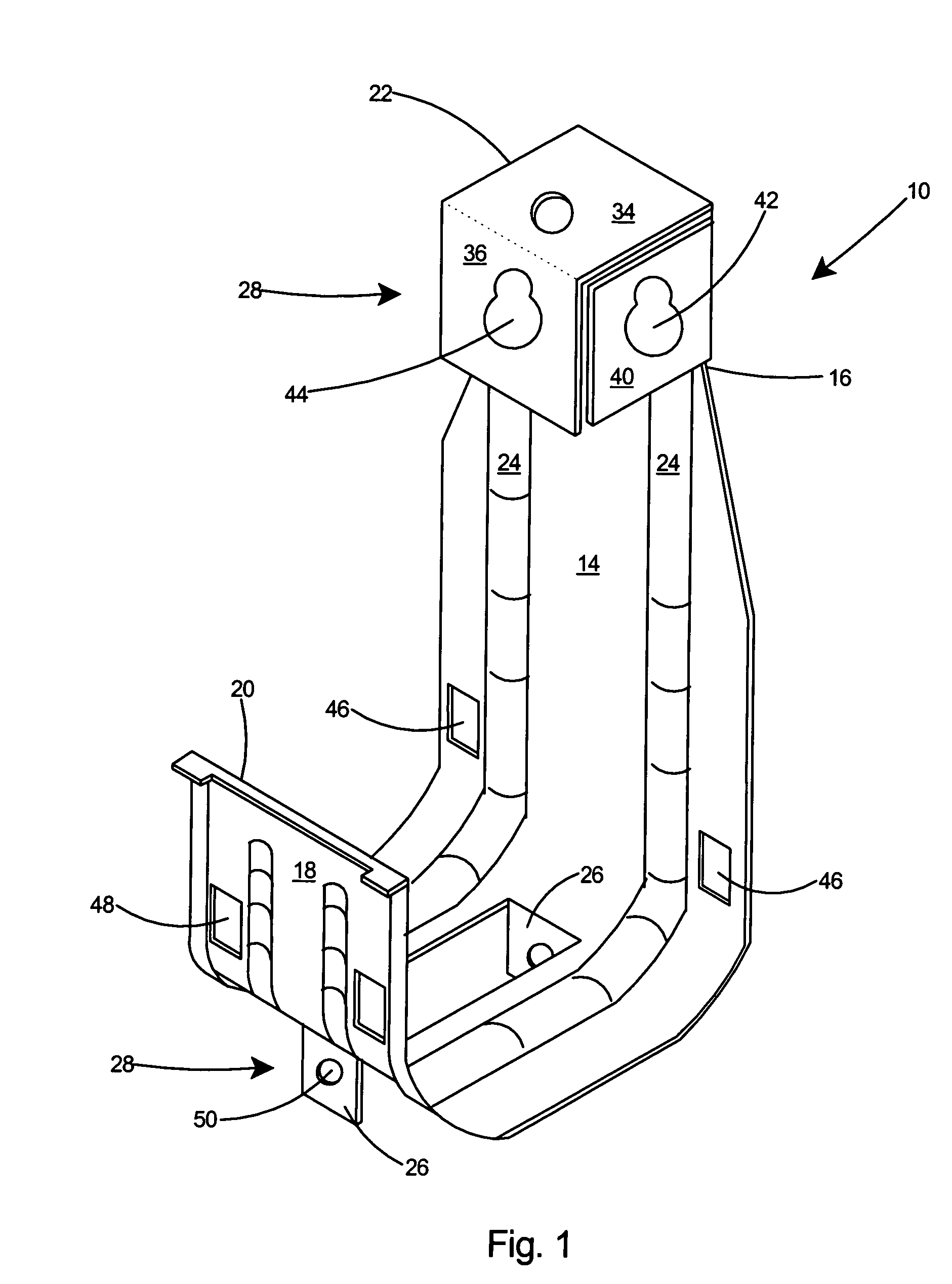
[0027]With reference to FIG. 1, there is shown a preferred embodiment of a cable support 10 according to the present invention. The cable support 10 includes a cable tray 12 and a rear wall 14 that extends vertically from the cable tray 12 to a top end 16. A front wall 18 extends vertically from the cable tray 12 to a top end 20. A box-shaped mounting assembly 22 projects substantially forward from the top end 16 of the rear wall 14. One or more stiffeners 24 extend along the rear wall 14, the cable tray 12, and the front wall 18. Two or more receiving tabs 26 extend downwardly from the cable tray 12. A fastening arrangement 28 is included in the box-shaped mounting assembly 22 and the receiving tabs 26 to enable two or more of the cable supports 10 to be joined together by aligning the receiving tabs 26 with the box-shaped mounting assembly 22 and fastening with the fastening arrangement 28.

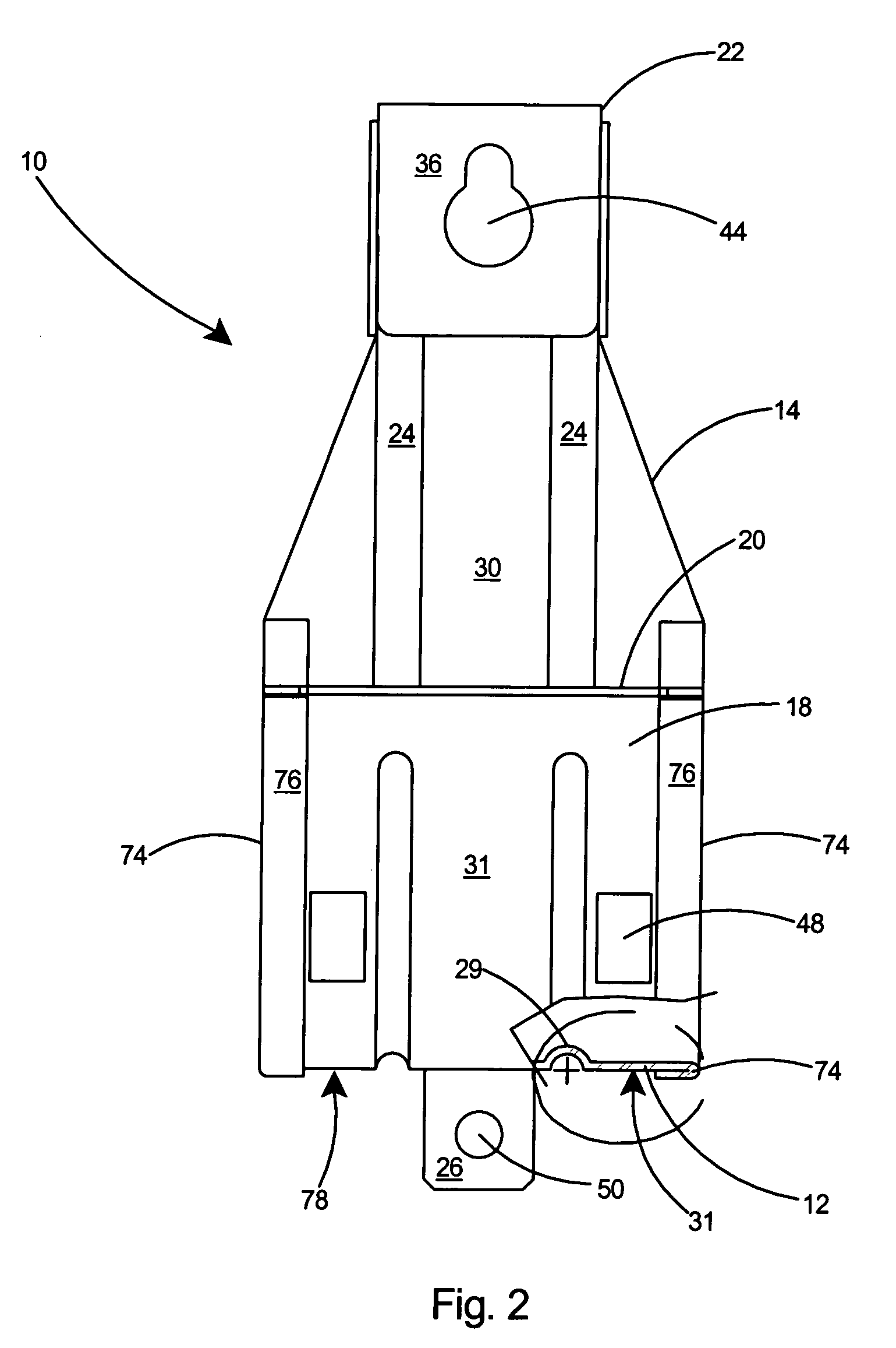
[0028]Referring to FIG. 2, as shown in the cutaway portion of the cable support 10 at the bo...


PUM


Abstract

A one-piece cable support having a box-shaped mounting assembly. The box-shaped mounting assembly extends over a cable tray portion of the cable support and includes several optional mounting apertures. Once secured to a building structure through the box-shaped assembly, the weight of a suspended bundle of cables is distributed evenly below the box-shaped assembly, thereby permitting the load to be balanced evenly below the assembly and reducing the bending moment and therefore the stress on the wall portion connecting the cable tray and mounting assembly portions of the support. A bracket assembly is provided on the bottom of the cable support to allow easy ganging of multiple cable supports without the need for specialized brackets. Stiffeners are included on the cable support to improve the withstanding of bending forces. A cable retaining arrangement secures cable bundles within the support.

Description

FIELD OF THE INVENTION[0001]This invention relates to cable supports for communications cables rated for high data transmission rates and specifically to a cable support with improved stiffness, an improved cable retaining arrangement, and the capability of being ganged together with additional like cable supports for supporting several bundles of cable.BACKGROUND OF THE INVENTION[0002]It is common to use high performance electrical telecommunication transmission cable to connect computers, servers, printers, faxes, and other electronic equipment. Unshielded twisted pair (UTP) cable has been developed to meet the high data transmission speeds needed in modern Local Area Networks (LAN). Many LANs today use Category 5 cable, the performance requirements of which are defined by the Electronic Industries Association (EIA) standard TSB-36 for UTP cable.[0003]As data transmission rates increase, to connect various pieces of electronic equipment, it frequently is necessary to route high sp...

Claims


Application Information

Patent Timeline
IPC IPC(8): E21F17/02
CPCF16L3/02H02G3/26F16L3/233
Inventor GRETZ, THOMAS J.
Owner ARLINGTON INDS
Why Eureka
Eureka Blog
Learn More