
Engine having variable valve mechanism

a valve mechanism and variable technology, applied in the field of engines, can solve the problems of difficult assembly of the hydraulic actuator and the rocker arm pistons, difficult to form the cylinder holes with high precision in a multi-cylinder engine, and little free space, and achieve the effect of easy assembly and high support rigidity

Active Publication Date: 2011-10-11
YAMAHA MOTOR CO LTD
View PDF10 Cites 14 Cited by
  • Summary
  • Abstract
  • Description
  • Claims
  • Application Information

AI Technical Summary

Benefits of technology

The present invention provides an engine with a camshaft and a variable valve mechanism that can easily be assembled. The camshaft has a high supporting rigidity and the variable valve mechanism can switch the lift degree of a valve between low and high speeds. The engine includes a cam carrier, rocker shaft, low and high speed rocker arms, and a switching device. The cam carrier has a cam bearing portion and a rocker shaft support, and the rocker shaft support is aligned with the cam bearing portion. The low speed rocker arm is swingably supported by the rocker shaft and swings according to the low speed cam of the camshaft to push a stem end surface of the valve. The high speed rocker arm is swingably supported by the rocker shaft, aligned with the low speed rocker arm and swings according to the high speed cam of the camshaft. The switching device is arranged to disconnect the low speed rocker arm and the high speed rocker arm in the low speed state and connect them in the high speed state. The engine also includes a hydraulic cylinder and a hydraulic piston in the cam bearing portion, which can be snugly inserted into a hole in the cam bearing portion or a separate hole. This reduces the size of the engine.

Problems solved by technology

The hydraulic actuator is provided between the valve springs in the valve mechanism but the spacing between the valve springs is small in a small size engine and therefore there is little free space.
Since the cylinder hole (hydraulic cylinder) is formed at the cylinder head, it is difficult to form the cylinder holes with high precision in a multi-cylinder engine.
It is also difficult to assemble the piston of the hydraulic actuator and the rocker arm.
In addition, the complicated oil passage is difficult to form.
However, the low speed rocker arm in the valve mechanism pushes two valves together in the same cylinder and therefore different lift degrees cannot be set for these valves.
In addition, the low speed rocker arm is provided at the bore center and therefore the camshaft cannot be supported at the bore center.
Therefore, the supporting rigidity of the camshaft is low and the valve mechanism is not suitable for high speed engines.

Method used


Image

  • Engine having variable valve mechanism
  • Engine having variable valve mechanism
  • Engine having variable valve mechanism

Examples


Embodiment Construction

[0022]Preferred embodiments of the present invention will be described in detail with reference to the accompanying drawings, in which the same or corresponding elements are designated by the same reference characters, and their description will not be repeated.

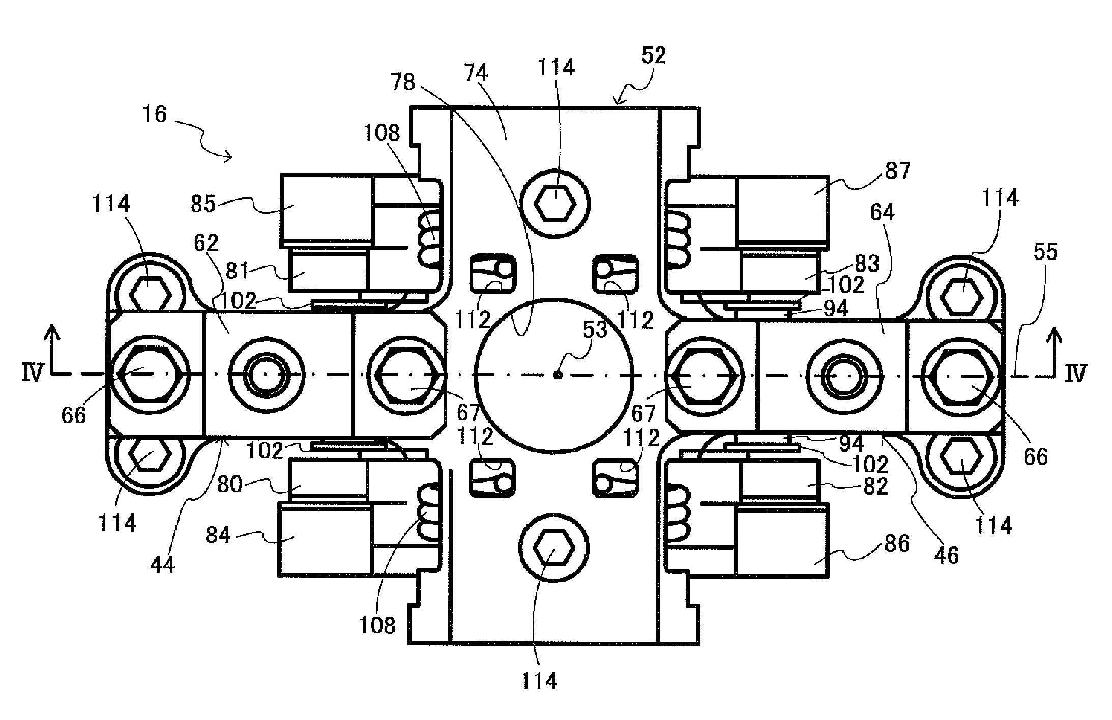
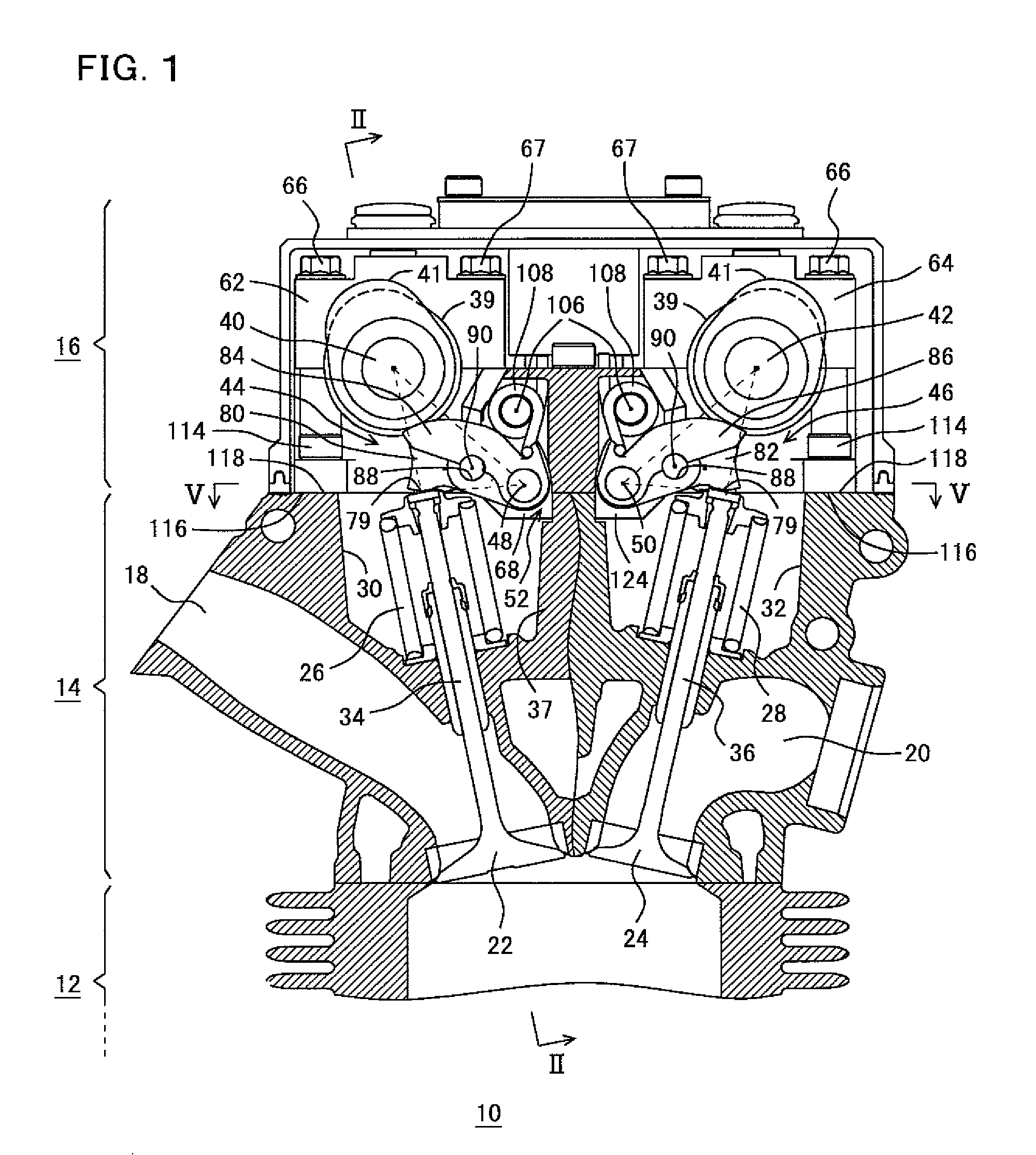
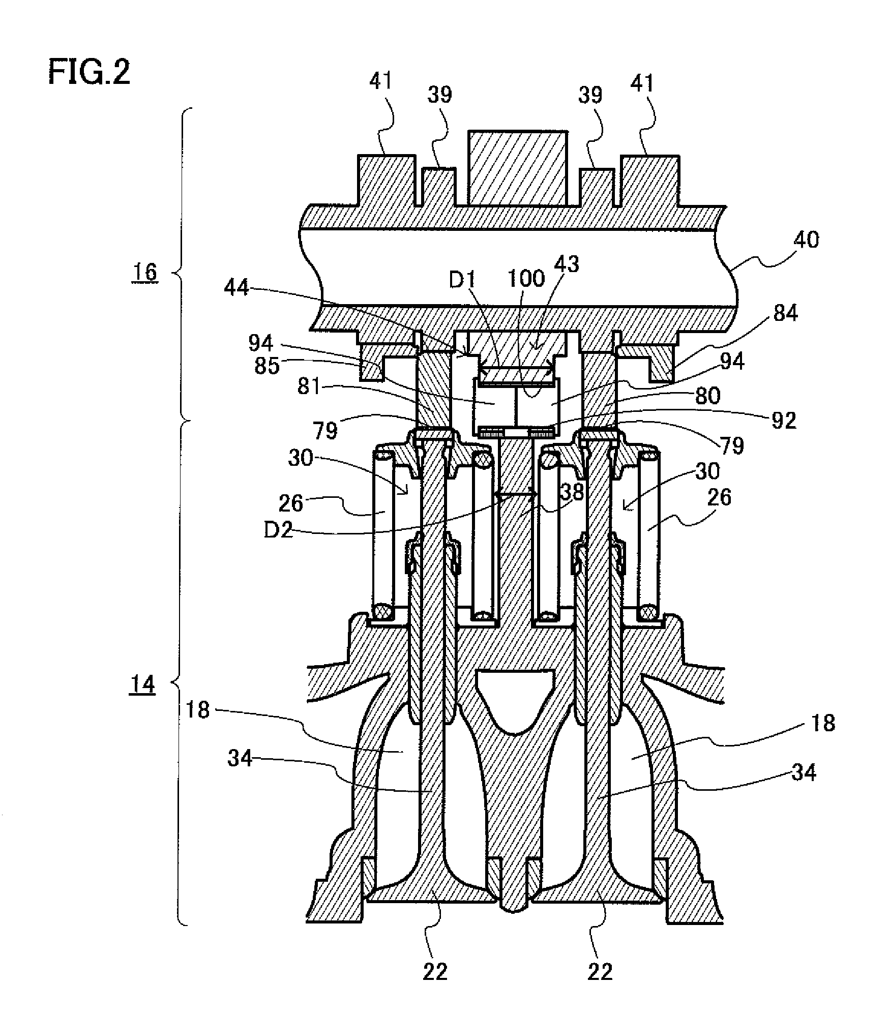
[0023]FIG. 1 is a sectional view of an engine according to a preferred embodiment of the present invention. FIG. 2 is a sectional view taken along line II-II in FIG. 1. FIG. 3 is a plan view of the cam carrier and various components assembled thereinto shown in FIG. 1. FIG. 4 is a sectional view taken along line IV-IV in FIG. 3. FIG. 5 is a sectional view taken along line V-V in FIG. 1. FIG. 6 is an exploded perspective view of the cam carrier and various components assembled thereinto shown in FIG. 1. FIG. 7 is a perspective view of the cam carrier shown in FIG. 6 and various elements assembled thereinto. FIG. 8 is a perspective view of the low speed rocker arm, the high speed rocker arm, the rocker shaft, the lost motion sp...


PUM


Abstract

An engine having a variable valve mechanism arranged to switch a lift degree of a valve between a low speed state and a high speed state includes a cam carrier defined by a cam bearing portion, a rocker shaft support, and a hydraulic cylinder support. The cam bearing portion is provided on a line passing through the bore center of a cylinder in a plane perpendicular or substantially perpendicular to the camshaft. The low speed rocker arm swings in response to the low speed cam of the camshaft. The high speed rocker arm swings in response to the high speed cam of the camshaft. The low speed rocker arm includes a through hole. A connecting pin is slidably inserted into the through hole and urged toward the hydraulic cylinder support. A hydraulic cylinder is provided in the hydraulic cylinder support.

Description

BACKGROUND OF THE INVENTION[0001]1. Field of the Invention[0002]The present invention relates to an engine, and more specifically to an engine having a variable valve mechanism arranged to switch a lift degree of a valve between a high speed state and a low speed state.[0003]2. Description of the Background Art[0004]JP 2002-303109 discloses a speed range selectable valve mechanism for an internal combustion engine. In this valve mechanism, a camshaft includes low and high cam noses, and a valve supported at a cylinder head is selectively engaged with one of the high and low cam noses by the cam-linkage, which allows the valve to be opened or closed according to the high and low speed ranges of the internal combustion engine. First and second rocker arms are pivotally supported at the cylinder head. The swinging end of the first rocker arm and the low cam nose are engaged with each other by the cam-linkage, and the swinging end of the second rocker arm and the high cam nose are engag...

Claims


Application Information

Patent Timeline
Patent Type & Authority Patents(United States)
IPC IPC(8): F01L1/34
CPCF01L1/185F01L13/0021F01L1/053Y10T74/20882Y10T74/2107
Inventor TAKAHASHI, TOSHIHIKOKOIKE, KAZUYA
Owner YAMAHA MOTOR CO LTD
Learn More