Eccentric oscillating reduction gear and stabilizer shaft rotating device using eccentric oscillating reduction gear

An eccentric swing and reducer technology, applied in transmission, gear transmission, transportation and packaging, etc., can solve the problem of high manufacturing cost

Inactive Publication Date: 2009-08-26
NABLESCO CORP
View PDF1 Cites 14 Cited by
  • Summary
  • Abstract
  • Description
  • Claims
  • Application Information

AI Technical Summary

Problems solved by technology

Thus, the manufacturing cost is high

Method used


Image

  • Eccentric oscillating reduction gear and stabilizer shaft rotating device using eccentric oscillating reduction gear
  • Eccentric oscillating reduction gear and stabilizer shaft rotating device using eccentric oscillating reduction gear
  • Eccentric oscillating reduction gear and stabilizer shaft rotating device using eccentric oscillating reduction gear

Examples


Embodiment 1

[0020] Hereinafter, Embodiment 1 of the present invention is described with reference to the drawings.

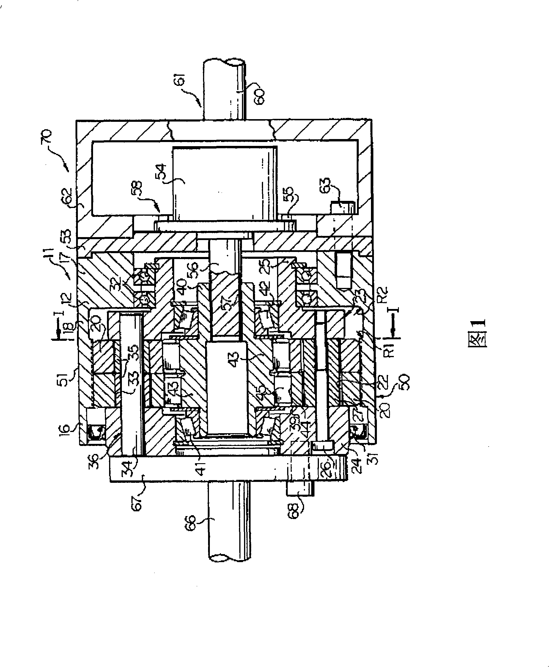
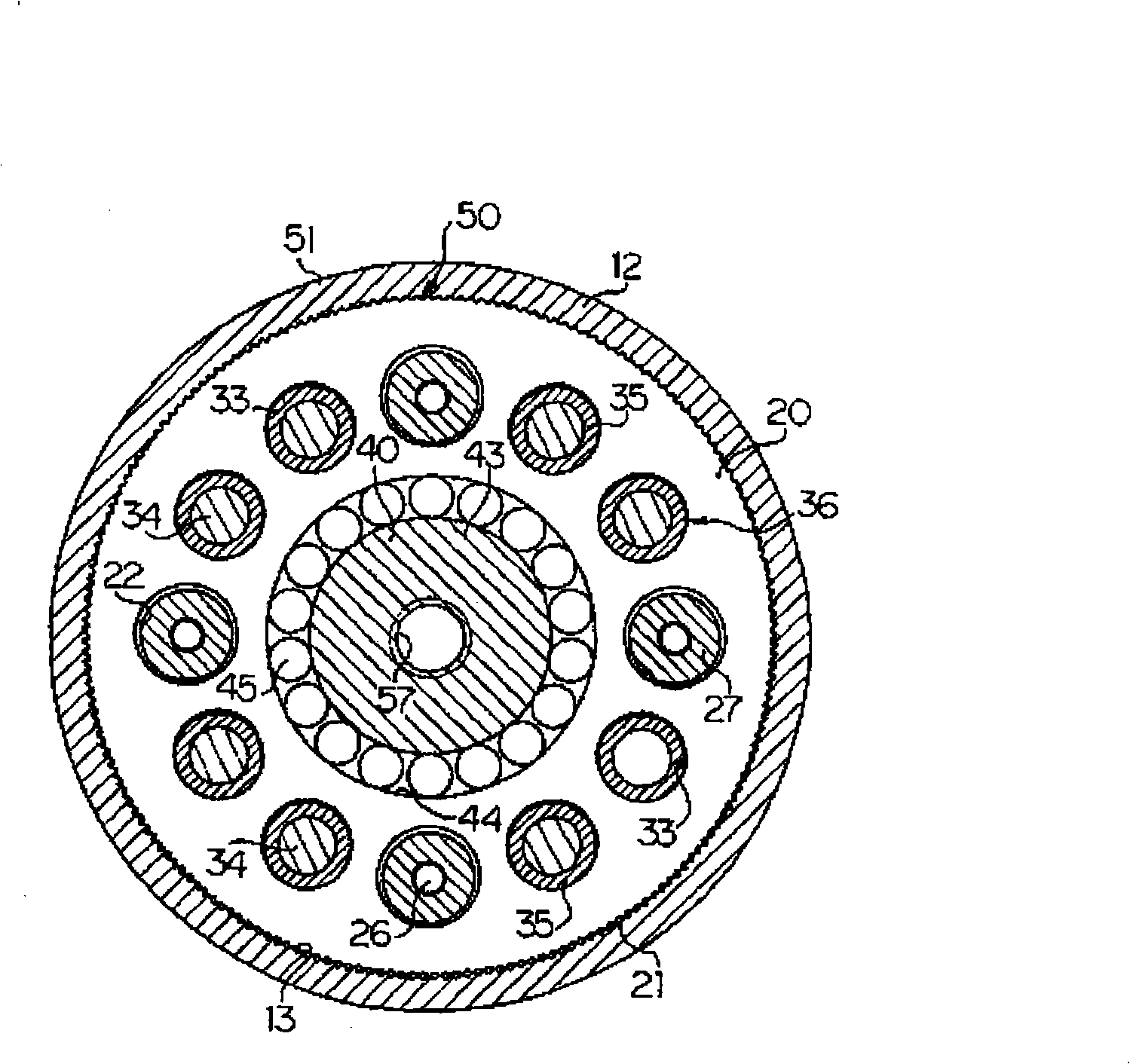
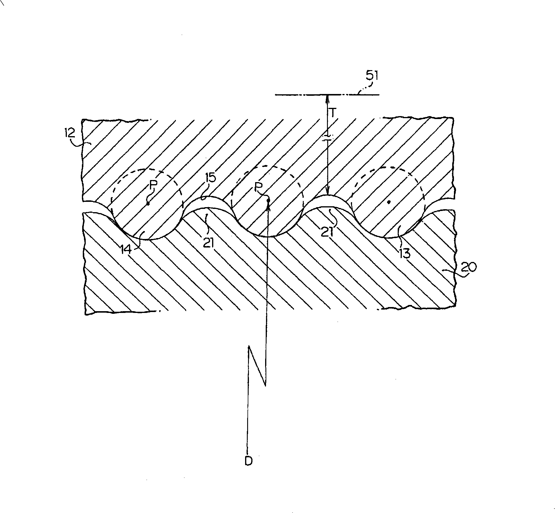
[0021] exist figure 1 , 2 In and 3, reference numeral 11 denotes an eccentric oscillating type speed reducer that reduces the input rotation speed and outputs the reduced rotation speed. The eccentric oscillating speed reducer 11 has a cylindrical housing 12 . Many internal teeth 13 whose inter-tooth curves extend in the axial direction are integrally formed, for example, by cutting using a hob or a shaper cutter, or by precision casting.

[0022] The internal teeth 13 are composed of a plurality of convex arc portions 14 and a plurality of concave arc portions 15, the convex arc portions 14 protrude radially inward and have an outer contour with a predetermined radius of curvature , each of the concave arc portions 15 is smoothly connected with the adjacent convex arc portion 14 and is radially recessed outward. Accordingly, the internal teeth 13 are formed by teeth ha...


PUM


Abstract

The present invention reduces the manufacturing cost of an eccentric oscillating type speed reducer 11 while preventing the torque transmitting capability of the eccentric oscillating type speed reducer 11 from being degraded. A part of a case 12, which is in a meshing region 50 in which internal teeth of the case 12 mesh with external teeth of pinions 20, is enabled to bend in a direction in which the radius of curvature thereof decreases. Thus, even when the concentration of a meshing load on the vicinity of a part, at which the manner of meshing between the internal teeth and the external teeth most differs from an ideal manner in the meshing region 50, a part of the case 12, which is in the vicinity of the part, bends in a direction in which the radius of curvature decreases. Consequently, the meshing load can be uniformized by being dispersed in the circumferential direction of the case 12.

Description

technical field [0001] The present invention relates to an eccentric oscillating type speed reducer that reduces an input rotation speed, and a rotating device for a stabilizer shaft using the eccentric oscillating type speed reducer. Background technique [0002] As a conventional eccentric oscillating type speed reducer, for example, the following speed reducer described in JP-B-5-86506 is known. [0003] This speed reducer has: a housing provided with internal teeth formed by pressing each of many cylindrical pins into substantially half of the inner circumference of the housing; and a bracket inserted into the housing. a body to enable relative rotation with respect to the housing; a pinion supported by the bracket so that external teeth formed on an outer periphery of the pinion mesh with the internal teeth; and a crank The crankshaft is configured to have an eccentric portion inserted into a central portion of the pinion and rotate to cause the pinion to rotate eccent...

Claims


Application Information

Patent Timeline
Patent Type & Authority Applications(China)
IPC IPC(8): F16H1/32B60G21/055
CPCF16H1/2818B60G2202/442B60G21/0555F16H1/32B60G2202/135B60G2204/4191B60G21/055
Inventor 王宏猷田中智
Owner NABLESCO CORP
Why Eureka
Try Eureka