Power transmission method of high-power wireless induction power supply system

a power transmission method and wireless induction technology, applied in the field of power supply systems, can solve the problems of inconvenient carrying and storage of many different mobile electronic products and the related battery chargers, high-power wireless induction power supply systems, and ineconomy to purchase respective battery chargers, so as to enhance power transmission efficiency, reduce the number of operating mosfet arrays, and enhance power transmission efficiency

Active Publication Date: 2011-12-01
FU TONG TECH
View PDF41 Cites 352 Cited by
  • Summary
  • Abstract
  • Description
  • Claims
  • Application Information

AI Technical Summary

Benefits of technology

[0014]It is another object of the present invention to provide a power transmission method for a high-power wireless induction power supply system consisting of a power-supplying module and a power-receiving module, which enables the power-supplying module to disperse the electric current passing therethrough subject to the use of multiple MOSFET arrays that are connected in parallel and operate at a high frequency, enhancing power transmission efficiency under a high power and high current operation, wherein the MOSFET arrays that are connected in parallel are independently operable so that the number of the operating MOSFET arrays can be reduced or increased subject to the demand of the load, minimizing power loss due to unnecessary switching operation and allowing carrying of sufficient current to drive a resonance circuit under a high power output.
[0015]It is still another object of the present invention to provide a power transmission method for a high-power wireless induction power supply system consisting of a power-supplying module and a power-receiving module, which utilizes a low-impedance resonant loop consisting of a parallelly connected capacitor array and power-supplying coil array for the resonance circuit of the power-supplying module to prohibit an abnormal temperature rise and to enhance power transmission efficiency during a high power output and passing of a large current. By using the known standard products of the capacitor array and the power-supplying coil array, the manufacturing cost of the high-power wireless induction power supply system is greatly reduced.
[0016]It is still another object of the present invention to provide a power transmission method for a high-power wireless induction power supply system consisting of a power-supplying module and a power-receiving module, which enables the microprocessor of the power-supply module to output a PWM (Pulse Width Modulation) signal to a first driver circuit / second driver circuit and to check the power output of the resonance circuit by means of a software, thereby adjusting the power output accurately and rapidly subject to the system demand. Further, the voltage of the power-supplying module is accurately controlled subject to regulation of the power output of the power-supplying module. Further, the filter circuit of the power-receiving module provides a two-step power filtration function. Subject to the operation of the software, the power-supplying module accurately and rapidly regulates its power output when the power-receiving module increases its power demand. The power-receiving module eliminates the use of any DC-DC Step-Down device, and therefore waste heat is minimized and conversion efficiency is enhanced.
[0018]It is still another object of the present invention to provide a power transmission method for a high-power wireless induction power supply system consisting of a power-supplying module and a power-receiving module, in which the microprocessor of the power-receiving module is capable of analyzing system voltage and current and providing a power demand signal to the power-supplying module during wireless power transmission operation so that the power-supplying module can regulate its power output accurately subject to the power demand of the power-receiving module and control the voltage within the target value. This power transmission method enables the output voltage of the power-receiving module to be well controlled without the use of any DC-DC step-down device, reducing power loss during voltage conversion and improving system operation efficiency.

Problems solved by technology

However, it is not economic to purchase a respective battery charger when buying a new mobile electronic product.
Further, it is inconvenient to carry and store many different mobile electronic products and the related battery chargers.
However, most commercial wireless induction power supply systems are for low power application, for example, for use in a mobile telephone or digital camera.
However, these high-power wireless induction power supply systems have drawbacks as follows:
1. During operation, the circuit board and its electronic components generate much waste heat, and the power-transmitting coils will also product heat, increasing safety risk.
Due to technical limitations, conventional techniques cannot fabricate a high-power power switch that operates at a high frequency for high power output.
Even if a high-power power switch that operates at a high frequency for high power output is available, the manufacturing cost will be extremely high.
The fabrication of resonance capacitor encounters the same problem.
3. The wireless power-transmitting and power-receiving induction coils of a high-power wireless induction power supply system must be accurately aligned. Further, the output electrical energy is fixed and not adjustable subject to the condition of the load. Therefore, conventional high-power wireless induction power supply systems have a low performance.
4. Conventional high-power wireless induction power supply systems are commonly designed to let the induction coil of the power-receiving end receive a voltage higher than the demand of the target at first and then to let the voltage be lowered to the level of the demand of the target by a DC-DC Step-Down IC. However, because voltage-down is achieved through switch means, energy loss will occur and interference noise and waste heat will be produced during each switching operation.

Method used


Image

  • Power transmission method of high-power wireless induction power supply system
  • Power transmission method of high-power wireless induction power supply system
  • Power transmission method of high-power wireless induction power supply system

Examples


Embodiment Construction

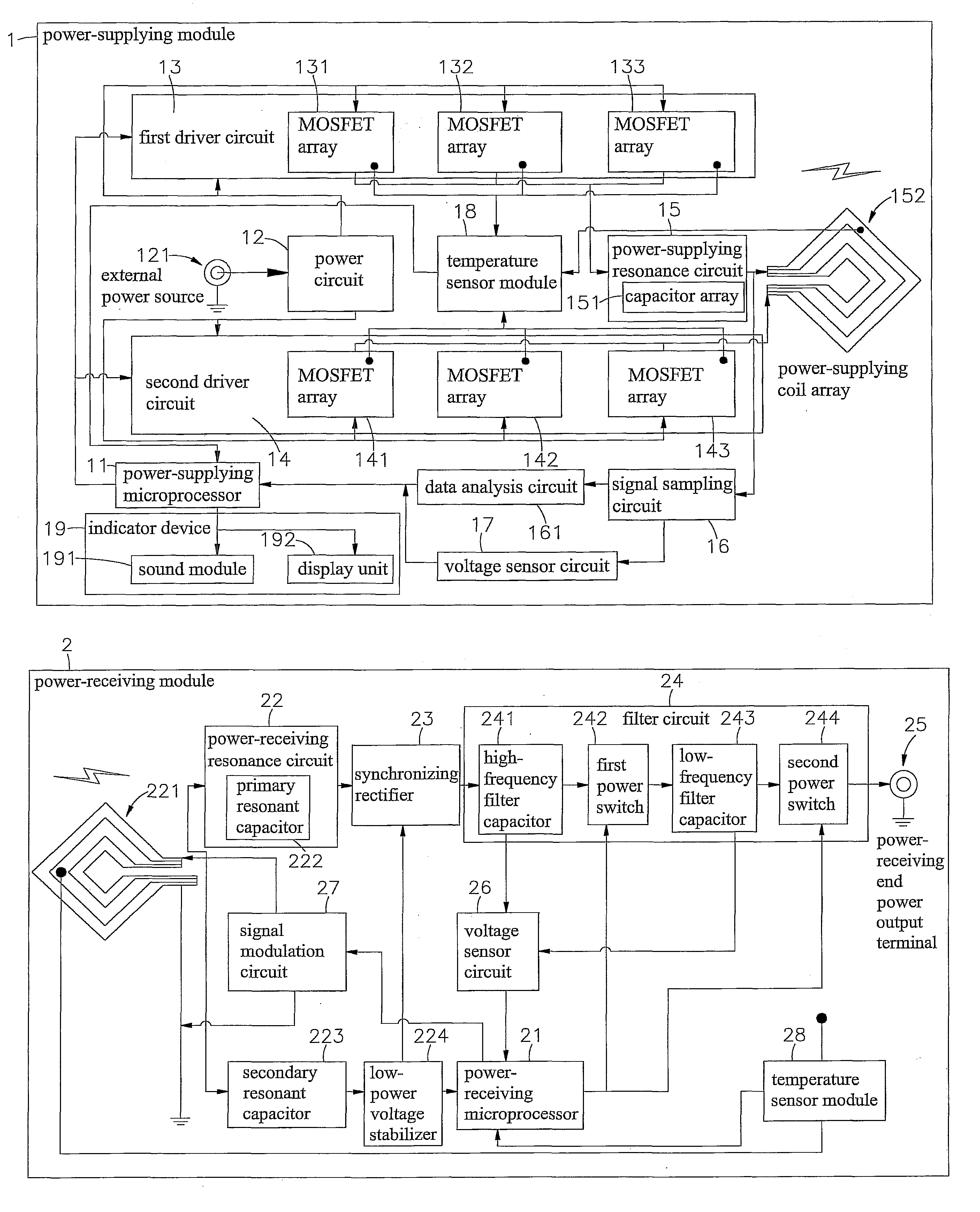
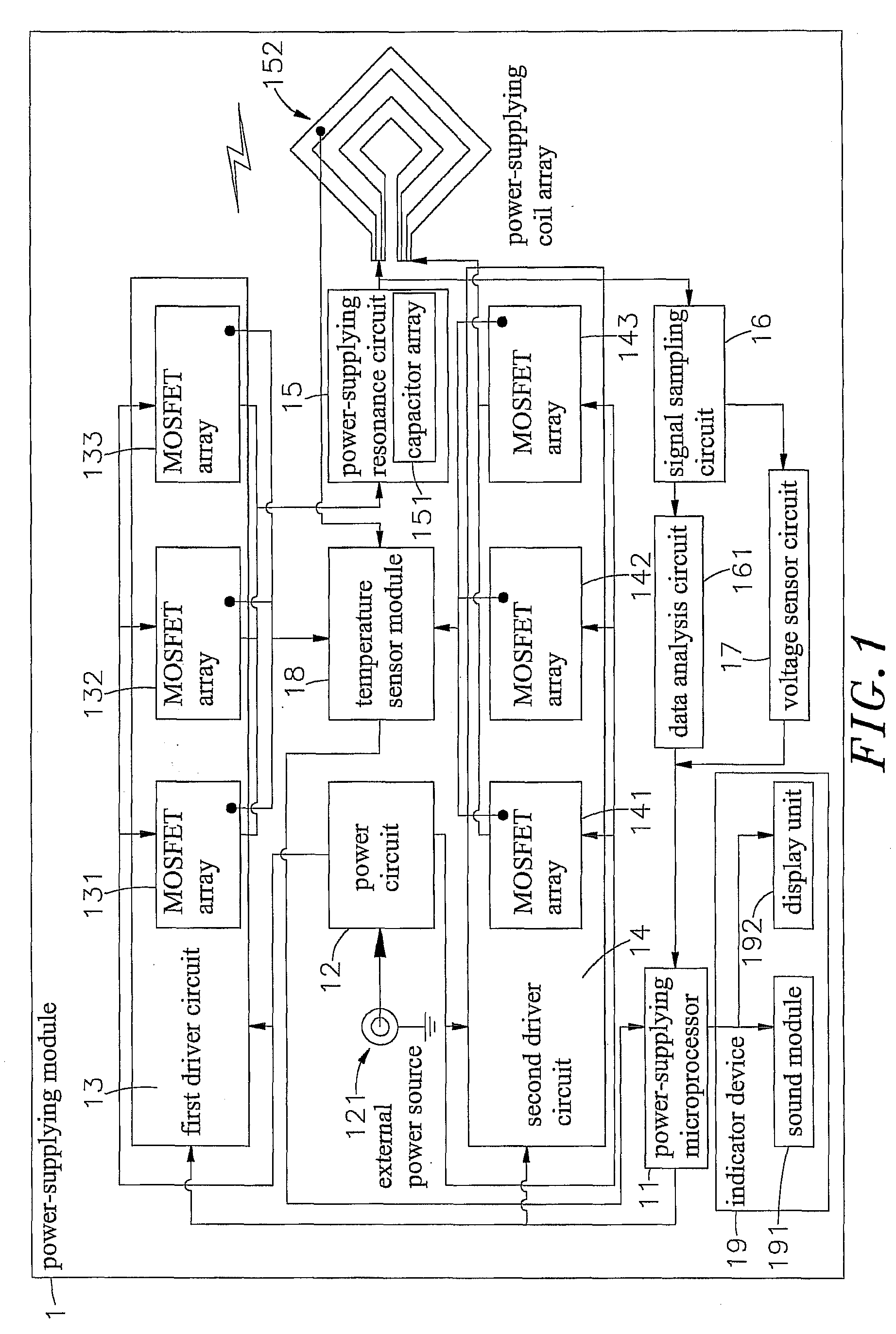
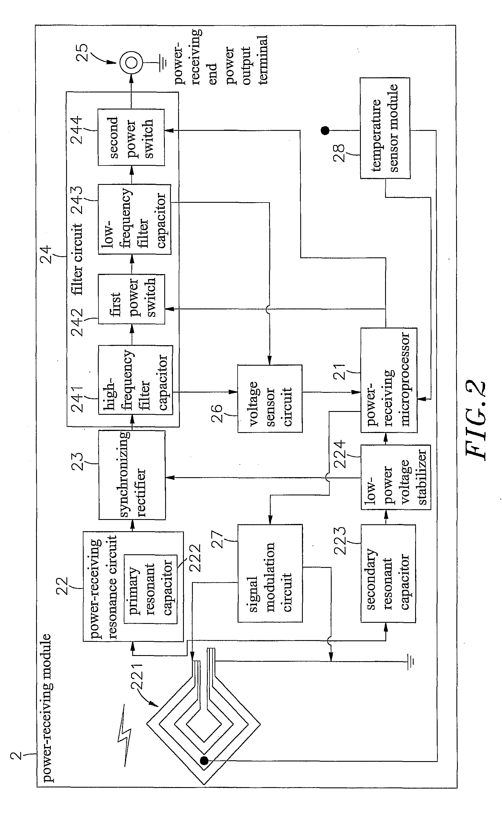
[0036]Referring to FIGS. 1 and 2, a high-power wireless induction power supply system is shown comprising a power-supplying module 1 and a power-receiving module 2.

[0037]The power-supplying module 1 comprises a power-supplying microprocessor 11 having installed therein an operation / control related software program and memory means, a power circuit 12 electrically connected to the power-supplying microprocessor 11 and electrically connectable to an external power source 121, a first driver circuit 13 and a second driver circuit 14 each consisting of a plurality of parallelly connected MOSFET (Metal-Oxide-Semiconductor Field-Effect Transistor) arrays 131;132;133 or 141;142;143 and electrically connected in parallel to the power-supplying microprocessor 11, a power-supplying resonance circuit 15 electrically connected to the first driver circuit 13 and consisting of a capacitor array 151 and a power-supplying coil array 152 that is adapted for receiving power supply from the second dri...


PUM


Abstract

A power transmission method used in a high-power wireless induction power supply system consisting of a power-supplying module and a power-receiving module is disclosed. The power-supplying module regulates its output energy by means of frequency modulation and driving power adjustment, enabling the energy to be received by the power-receiving module and transmitted through a power-receiving coil array and a primary resonant capacitor and a secondary resonant capacitor of power-receiving resonance circuit, a synchronizing rectifier, a low-power voltage stabilizer, a high-frequency filter capacitor, a first power switch, a low-frequency filter capacitor and a second power switch of a filter circuit for output to an external apparatus.

Description

[0001]This application claims the priority benefit of Taiwan patent application number 099117430, filed on May 31, 2010.BACKGROUND OF THE INVENTION[0002]1. Field of the Invention[0003]The present invention relates to power supply systems and more particularly, to a power transmission method of high-power wireless induction power supply system, which employs frequency modulation technique and multi-array architecture to regulate the Output power subject to the condition of the load, ensuring high level of safety and efficiency in wireless power transmission.[0004]2. Description of the Related Art[0005]Following fast development of electronic and internet technology, many digitalized electronic products, such as digital camera, cellular telephone, multimedia player (MP3, MP4) and etc., have been continuously developed and have appeared on the market. These modern digital electronic products commonly have light, thin, short and small characteristics.[0006]However, for high mobility, po...

Claims


Application Information

Patent Timeline
Patent Type & Authority Applications(United States)
IPC IPC(8): H02J17/00
CPCH02J17/00H02J50/12H02J50/80H02J50/402
Inventor TSAI, MING-CHIUCHAN, CHI-CHE
Owner FU TONG TECH
Why Eureka
Try Eureka