Continuously variable transmission apparatus

a transmission apparatus and continuously variable technology, applied in the direction of belts/chains/gearings, friction gearings, belts/chains/gearings, etc., can solve the problems of poor transmission efficiency of single-cavity toroidal-type continuously variable transmission, reducing the design freedom of the transmission for a small-sized car, and reducing the axial direction of the whole continuously variable transmission apparatus. , the effect of saving space for arranging

Active Publication Date: 2006-08-22
NSK LTD
View PDF15 Cites 118 Cited by
  • Summary
  • Abstract
  • Description
  • Claims
  • Application Information

AI Technical Summary

Benefits of technology

[0032]According to the above-structured continuously variable transmission apparatus of the invention, since the center axis of the toroidal-type continuously variable transmission is disposed such that it is shifted in the diameter direction from the center axes of the first, second and third planetary-gear-type transmissions, the axial-direction dimension of the whole of the continuously variable transmission apparatus can be reduced. Also, because there can be realized a state in which the output shaft can be stopped while the input shaft is left rotating, that is, a state in which the transmission ratio can be set infinite, there can be eliminated the need to incorporate a start mechanism such as a torque converter into the continuously variable transmission apparatus separately. Further, the number of clutches, which are used to constitute the switching mechanism for switching the modes, can also be reduced. Still further, as the rotation shafts to be disposed in parallel to each other (shifted in the diameter direction from each other) in the continuously variable transmission apparatus portion, there may be disposed, in addition to the input shaft, only the rotation transmission shaft and output shaft (and the hollow rotation shafts disposed on the peripheries of the rotation transmission shaft and output shaft). This can save the space for arranging the rotation shafts, thereby being able to reduce the section area (regarding planes at right angles to the rotation shafts) of the continuously variable transmission apparatus. This makes it possible to realize a continuously variable transmission apparatus which is small in size and excellent in transmission efficiency.

Problems solved by technology

Therefore, the above-mentioned conventional continuously variable transmission apparatus is not fit for a transmission for a front engine front drive car which has been widely spread mainly in the field of a small-sized car.
However, as known widely, the single-cavity-type toroidal-type continuously variable transmission is poorer in transmission efficiency than the double-cavity-type toroidal-type continuously variable transmission shown in FIGS. 3 and 4.
Due to this, the section area of the whole of the continuously variable transmission apparatus becomes large, which lowers the freedom of design thereof as a transmission for a small-sized car.
Due to this, the size of the whole of the continuously variable transmission apparatus becomes rather large, which makes it considerably difficult to employ the continuously variable transmission apparatus as a transmission for a small-sized FF car.

Method used


Image

  • Continuously variable transmission apparatus
  • Continuously variable transmission apparatus
  • Continuously variable transmission apparatus

Examples


Embodiment Construction

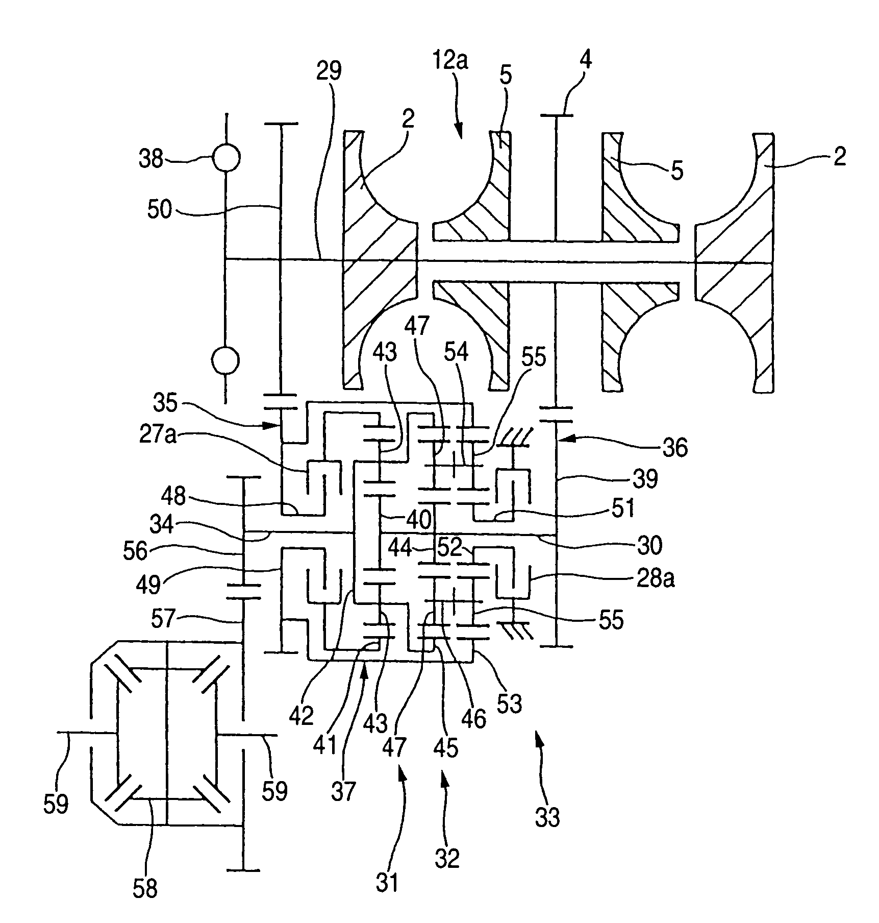
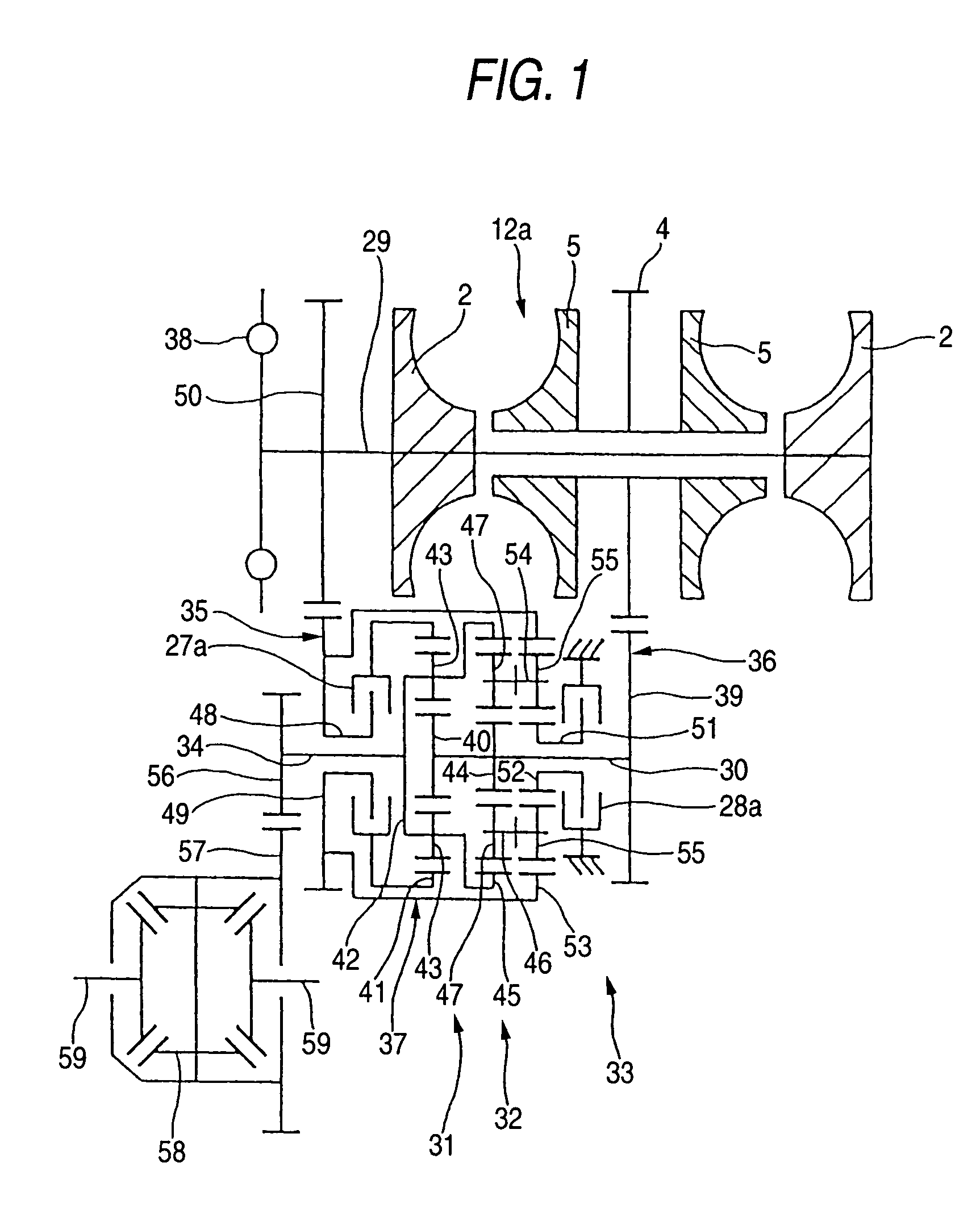
[0037]FIG. 1 shows a first embodiment of a continuously variable transmission apparatus according to the invention. The continuously variable transmission apparatus according to the present embodiment comprises an input shaft 29, a toroidal-type continuously variable transmission 12a, a rotation transmission shaft 30, first, second and third planetary-gear-type transmission 31, 32 and 33, an output shaft 34, first, second and third power transmission mechanisms 35, 36 and 37, and a low-speed clutch 27a and a high-speed clutch 28a respectively constituting a switching mechanism. Of these composing elements, the input shaft 29 is connected to the crankshaft of an engine through a damper joint 38, so that the input shaft 29 can be driven and rotated by this engine.

[0038]The toroidal-type continuously variable transmission 12a is similar in structure to the conventional structure shown in the above-discussed FIG. 3 and includes a pair of input side disks 2, 2 which can be rotated togeth...


PUM


Abstract

A continuously variable transmission apparatus, has: an input shaft; a toroidal-type continuously variable transmission; a rotation transmission shaft; first, second and third planetary-gear-type transmissions; a first power transmission mechanism; a second power transmission mechanism; a third power transmission mechanism; and, a switching mechanism, wherein the second sun gear and one of the first and third sun gears are rotated together with the rotation transmission shaft to thereby execute the power transmission through the rotation transmission shaft and one of the first and second planetary-gear-type transmissions, and, in a state where the power transmission through the third planetary-gear-type transmission is cut off, in accordance with the control of the transmission ratio of the toroidal-type continuously variable transmission, the output shaft is stopped while the input shaft is rotating.

Description

BACKGROUND OF THE INVENTION[0001]1. Technical Field of the Invention[0002]The present invention relates to an improvement in a continuously variable transmission apparatus incorporating therein a toroidal-type continuously variable transmission for use as an automatic transmission apparatus for a car.[0003]2. Description of the Related Art[0004]As an automatic transmission apparatus for a car, use of such a toroidal-type continuously variable transmission as shown in FIG. 3 has been studied and enforced in part of the car industry. This is referred to as a toroidal-type continuously variable transmission of a double-cavity type, in which, on the peripheries of the two end portions of an input shaft 1, there are supported two input side disks 2, 2 through their associated ball splines 3, 3. Therefore, the two input side disks 2, 2 are respectively supported so as to be concentric with each other and can be rotated in synchronization with each other. Also, on the periphery of the midd...

Claims


Application Information

Patent Timeline
Patent Type & Authority Patents(United States)
IPC IPC(8): F16H15/50F16H37/02F16H37/08
CPCF16H37/086F16H2037/0886
Inventor INOUE, EIJI
Owner NSK LTD
Why Eureka
Try Eureka