
Liquid cooling system for a rack-mount server system

a server system and liquid cooling technology, applied in the field of rack-mount server systems, can solve the problems of reducing cooling efficiency, air heated by the exhausted air from the devices, and inability to achieve the desired cooling effect, so as to prevent the variation in flow quantity, stable cooling performance, and stable cooling performance

Active Publication Date: 2008-01-15
MAXELL HLDG LTD
View PDF8 Cites 130 Cited by
  • Summary
  • Abstract
  • Description
  • Claims
  • Application Information

AI Technical Summary

Benefits of technology

[0009]Meanwhile, in the rack-mount system as described above, other devices are similarly mounted above and below the devices of the server module. Therefore, even in the case where the air is taken in and out through the top and bottom plates, the intake and exhaust vents are obstructed and thus it is impossible to achieve the desired cooling effects. Furthermore, in the case where the intake vents are provided on the side face of the devices, the air heated by the exhausted air from the devices is taken in and the cooling efficiency is reduced. Therefore, in the forced air cooling system for the rack-mount system, it is necessary that the air is taken in from the front face of the devices and exhausted from the rear face or the side faces.
[0010]Also, in the rack-mount system, the reduction in thickness of the devices has advanced in recent years so as to achieve the higher density mounting and the space saving of the server modules in the rack cabinet, and the cooling fan mounted in the device is limited to the small cooling fan with a small flow rate. In addition, since devices such as magnetic storage devices are mounted on the front face of the devices and connectors to the outside are arranged on the rear face of the devices, the area for the air intake and exhaust is significantly reduced.
[0011]Also, with the performance development of the server module in the rack-mount system, the performance of CPU or LSI is enhanced, the multiple CPU configuration is increasingly used, and devices such as the magnetic storage devices are operated at higher speed and formed into an array. As a result, the amount of heat generated therein is increased. Therefore, it becomes more and more difficult to ensure the air flow rate required in the forced air cooling.
[0012]Accordingly, an object of the present invention is to provide the cooling method capable of achieving the cooling enough to ensure the reliability of the server modules mounted in the rack cabinet without losing the advantages of the rack-mount system and capable of achieving the smooth radiation of the heat from the high-temperature components mounted on the server module particularly by adopting the liquid cooling system even in the case where the performance of the server module is advanced, the thickness the server module is reduced, and the high density mounting technology is advanced.
[0020]Also, in order to prevent the variation in flow quantity and ensure the stable cooling performance even in the case where a plurality of server modules are connected to the pipes provided on the rack cabinet side, a pump is incorporated in each of the devices of the server modules so that they can supply and drain the coolant from and to the pipes on the rack cabinet side by itself.
[0021]In addition, in this cooling system, in order to provide the stable cooling performance, the function to detect the temperature of the circulating coolant and control the power of the heat exchanger is given to the cooling unit using the heat exchanger, and thus, the temperature of the coolant passing through the cooling unit can be kept at a constant temperature.

Problems solved by technology

Therefore, even in the case where the air is taken in and out through the top and bottom plates, the intake and exhaust vents are obstructed and thus it is impossible to achieve the desired cooling effects.
Furthermore, in the case where the intake vents are provided on the side face of the devices, the air heated by the exhausted air from the devices is taken in and the cooling efficiency is reduced.
Also, in the rack-mount system, the reduction in thickness of the devices has advanced in recent years so as to achieve the higher density mounting and the space saving of the server modules in the rack cabinet, and the cooling fan mounted in the device is limited to the small cooling fan with a small flow rate.
Therefore, it becomes more and more difficult to ensure the air flow rate required in the forced air cooling.

Method used


Image

  • Liquid cooling system for a rack-mount server system
  • Liquid cooling system for a rack-mount server system
  • Liquid cooling system for a rack-mount server system

Examples


Embodiment Construction

[0040]Hereinafter, embodiments of the present invention will be described in detail with reference to the accompanying drawings. Note that components having the same function are denoted by the same reference symbols throughout the drawings for describing the embodiments, and the repetitive description thereof is omitted.

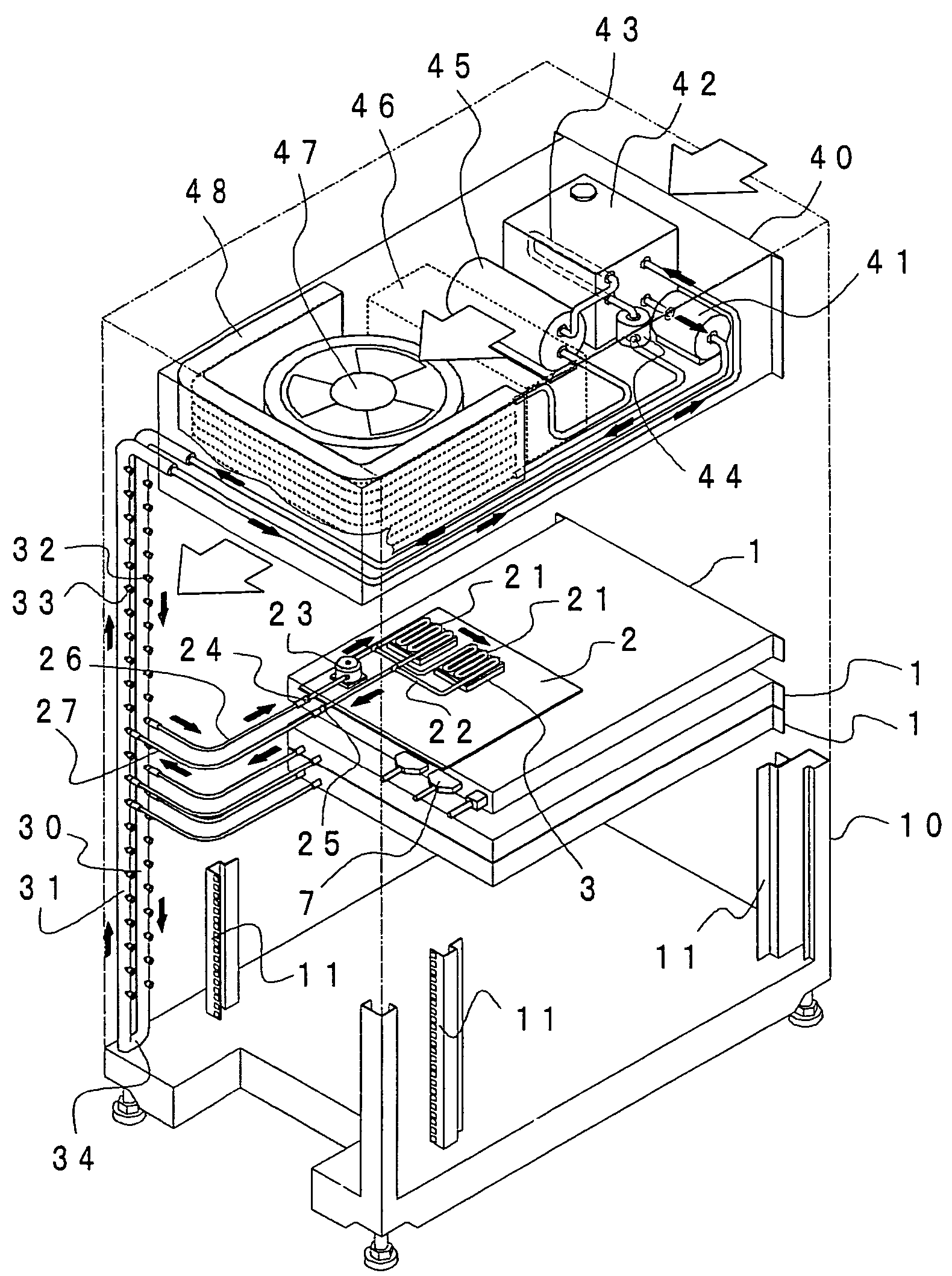
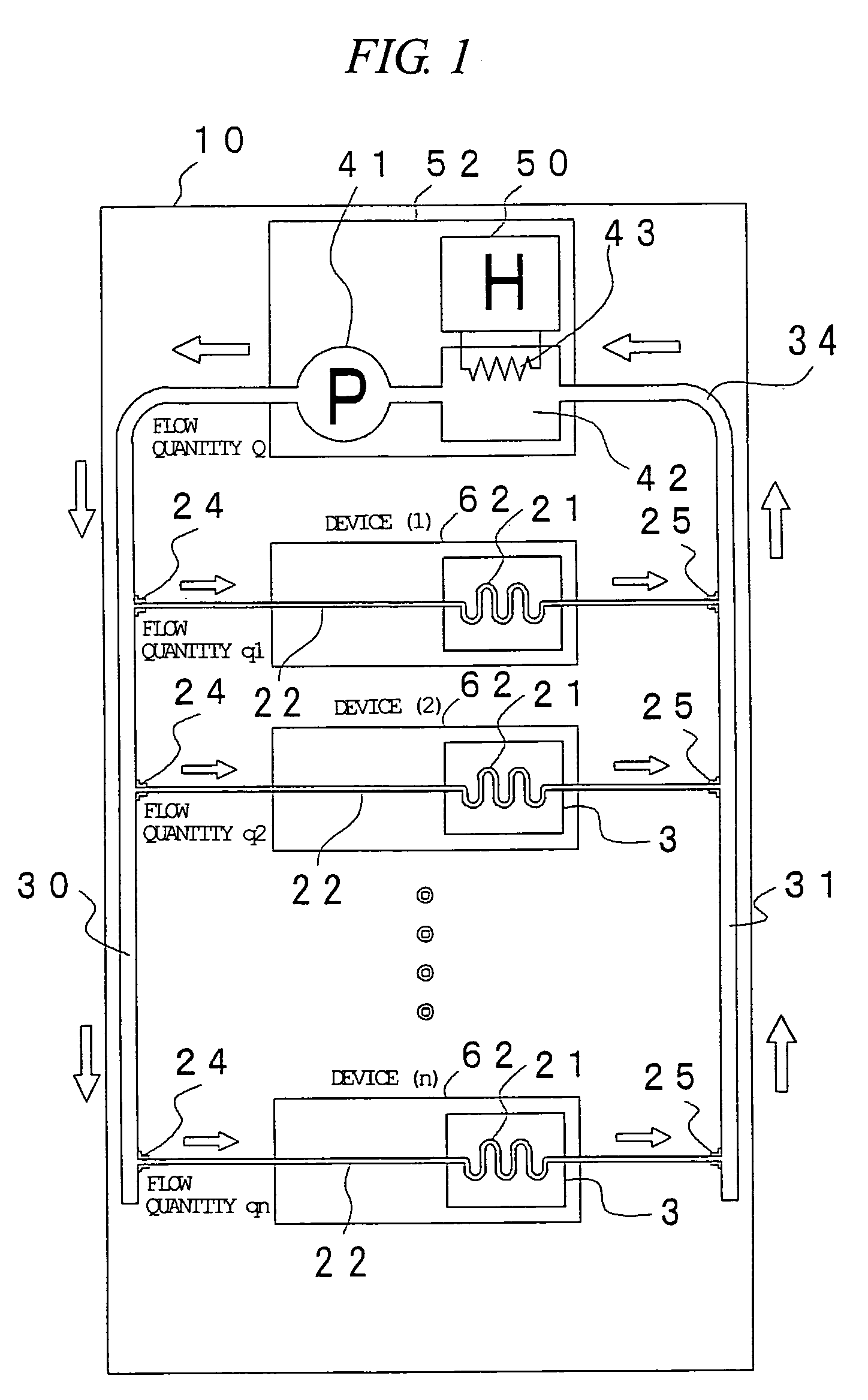
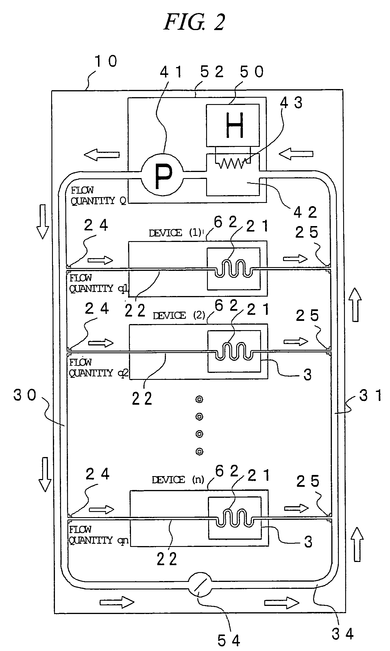
[0041]First, examples of the configuration of the cooling system for the rack-mount server system according to an embodiment of the present invention will be described with reference to FIGS. 1 to 4. FIG. 1 shows the case where the bypass route is not provided, FIG. 2 shows the case where the bypass route is provided and a pump is not mounted on each device of the server module, FIG. 3 shows the case where the bypass route is provided and a flow control valve is provided in each device of the server module, and FIG. 4 shows the case where the bypass route is provided and the pump is mounted on each device of the server module.

[0042]The configuration of the cooling s...


PUM


Abstract

A rack-mount server system of a liquid cooling system, in which a heat-generating component such as a CPU is cooled by a coolant has a plurality of server modules with heat-generating components which are cooled by the circulating coolant. The server modules are connected in parallel to a circulation coolant path through which the coolant to cool the server modules is circulated. In the middle of the coolant circulation path is a cooling unit that cools the coolant by radiating its heat to the outside air. Furthermore, a bypass route parallel to the server modules and going around the server modules is provided in the coolant circulation path, and the circulation quantity of the coolant is controlled in the bypass route. Alternatively, the flow quantity of the coolant is controlled in each of the server modules.

Description

BACKGROUND OF THE INVENTION[0001]The present invention relates to a cooling method for a rack-mount server system in which a plurality of computers are stacked. More particularly, the present invention relates to a technique effectively applied to the liquid cooling system in which a coolant is circulated.[0002]In recent years, the rack-mount system has been the mainstream in the system configuration, storage, and installation of a data processing system such as a server. In the rack-mount system, the devices with specific functions are mounted so that they are stacked on each other in a rack cabinet formed based on a particular standard, and the rack-mount system has the advantages as follows: the devices can be freely selected and arranged, the rack-mount server system is excellent in the flexibility and extensibility of the system configuration, and the space occupied by the system can be reduced.[0003]Particularly, the 19 inch rack cabinet defined in the IEC standard (Internatio...

Claims


Application Information

Patent Timeline
IPC IPC(8): F25D23/12G06F1/20H05K7/18H05K7/20
CPCH05K7/20781G06F2200/201E04G17/0658
Inventor OTA, SHIGEMIMATSUSHITA, SHINJI
Owner MAXELL HLDG LTD
Learn More