Radar system with phase based multi-target detection

Active Publication Date: 2016-03-24
APTIV TECH LTD
View PDF31 Cites 93 Cited by
  • Summary
  • Abstract
  • Description
  • Claims
  • Application Information

AI Technical Summary

Benefits of technology

[0003]Automotive systems such as Autonomous Intelligent Cruise Control, Collision Warning and Mitigation, and Blind Spot Detection use a radar sensor to detect objects proximate to the vehicle. Reflected radar signals are detected by an antenna array are typically converted to a discreet base band, then transformed from the time-domain to the frequency-domain where amplitude profiles indicative of each signal detected by each receive antenna element are integrated non-coherently. Automotive radars often use this non-coherently integrated (NCI) amplitu

Problems solved by technology

However, NCI-detection techniques have performance limitations for detection and discrimination of multiple objects that are near each other.
That is, if two objects have similar position and Doppler characteristics, and the reflection characteristics or Radar Cross Sections (RCS) to the objects are significantly different, then the reflected radar signal from the object with the larger RCS may mask the reflected radar signal from target with smaller RCS, and thereby makes second target identification and/or discrimination difficult.
However, these options undesirably increase sensor size, cost, and signal processing complexity.
Furthermore, it has been o

Method used


Image

  • Radar system with phase based multi-target detection
  • Radar system with phase based multi-target detection
  • Radar system with phase based multi-target detection

Examples


Embodiment Construction

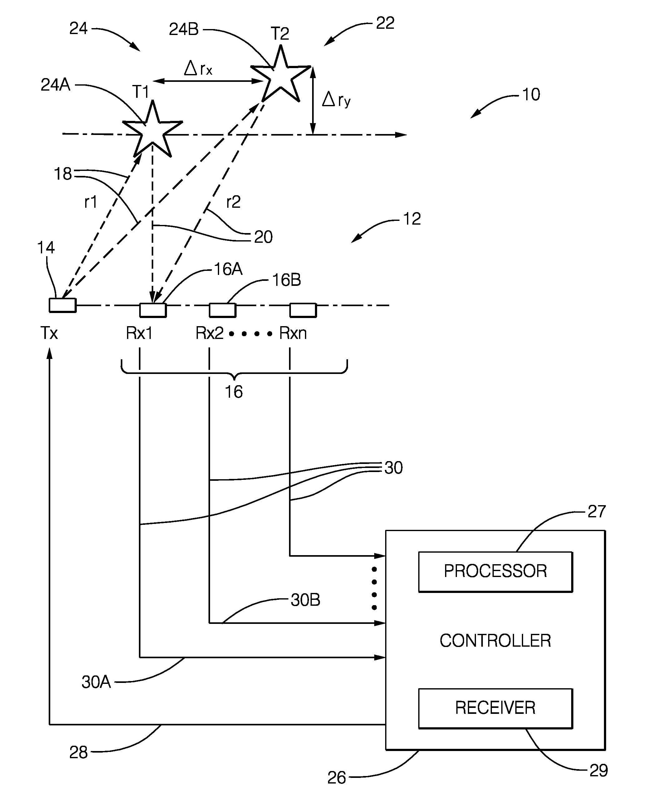
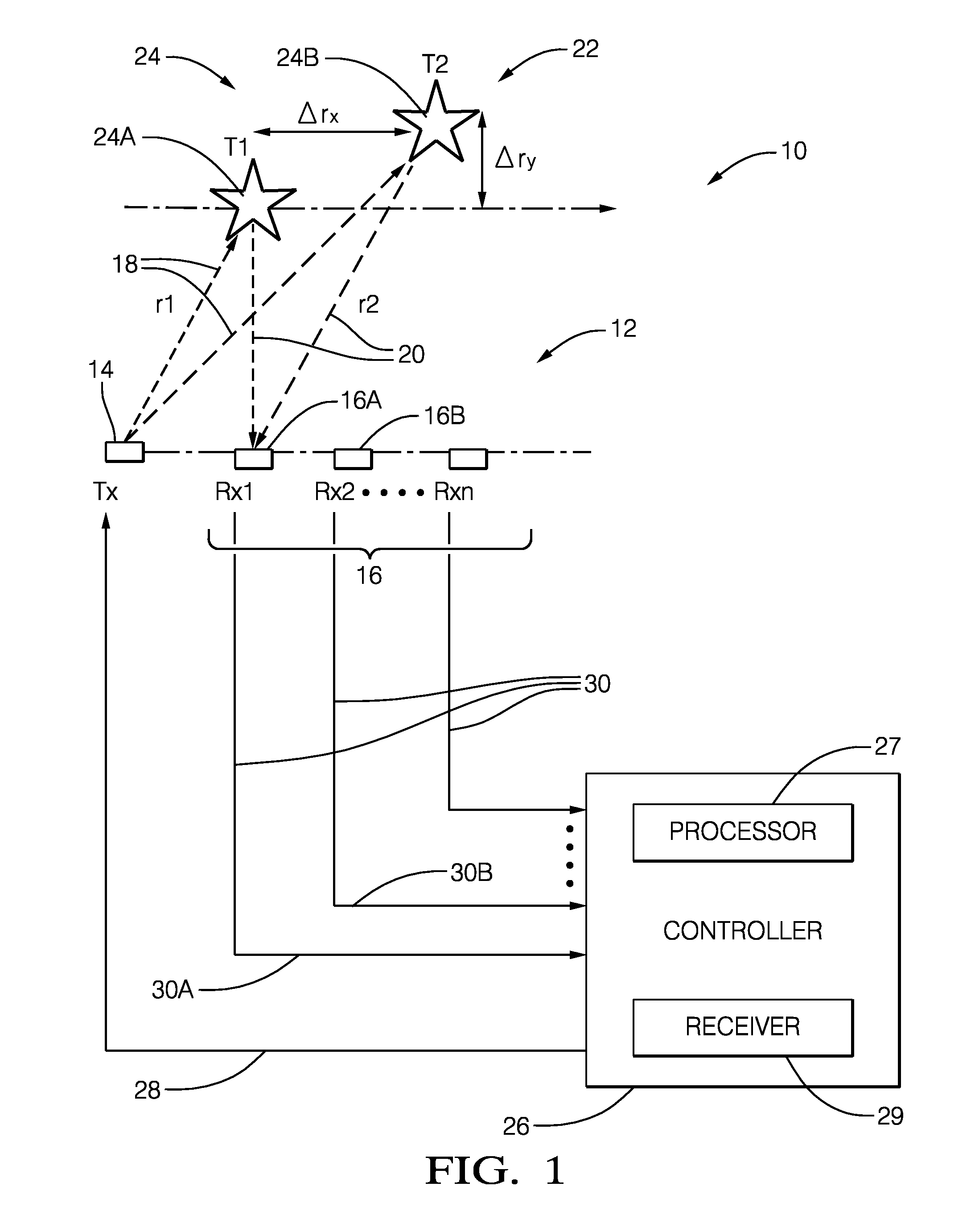
[0023]FIG. 1 illustrates a non-limiting example of a radar system, hereafter referred to as the system 10. The system 10 includes an antenna array 12 that may include a transmit-element 14, and an array of receive elements, hereafter referred to as a plurality of antennas 16. It is recognized that one or more of the antenna elements that make up the antenna array 12 could be used to both transmit a radar signal 18, and output a detected signal 30 indicative of reflected radar signals 20 reflected by a first object 24A or a second object 24B in a field-of-view 22 of the system 10. The transmit-element 14 and the plurality of antennas 16 are illustrated as distinct elements in this example only to simplify the explanation of the system 10.

[0024]The system 10 may also include a controller 26 configured to output a transmit-signal 28 to the transmit-element 14, and configured to receive detected signals 30 from each antenna, for example a first signal 30A from a first antenna 16A and a ...


PUM


Abstract

A radar system includes a plurality of antennas and a controller. The plurality of antennas is configured to detect a reflected radar signal reflected by an object in a field-of-view of the system. Each antenna of the plurality of antennas is configured to output a detected signal indicative of the reflected radar signal detected by the antenna. The controller is configured to receive detected signals from the plurality of antennas, and determine if a target is present in the field-of-view based on the detected signals. The controller is also configured to determine if the target includes more than one object based on an analysis of phases of the detected signals.

Description

TECHNICAL FIELD OF INVENTION[0001]This disclosure generally relates to a radar system, and more particularly relates to a system that determines if a target includes more than one object based on a comparison of phases of detected signals from multiple receive antennas.BACKGROUND OF INVENTION[0002]Because of antenna size, system size, technology, and cost constraints, automotive radar sensors may have performance limitations with regard to discriminating two objects that have similar position and Doppler shift characteristics, or if one object has a substantially larger Radar Cross Section (RCS) than a second nearby object. Examples of two objects with similar range and Doppler shift reflection characteristics that typical automotive radar systems have difficulty discerning include: a slowly moving pedestrian walking around stationary or slowly moving passenger vehicle, a motor cycle traveling beside a tractor-trailer traveling in an adjacent lane at a similar range and range rate, ...

Claims


Application Information

Patent Timeline
IPC IPC(8): G01S7/41G01S13/931
CPCG01S7/41G01S13/02G01S13/88G01S7/354G01S7/414G01S13/42G01S13/584G01S13/726G01S13/931G01S7/2921G01S7/412G01S13/4454G01S2013/0245
Inventor ARAGE, ALEBEL, HASSEN
Owner APTIV TECH LTD
Why Eureka
Try Eureka