Video input processor, imaging signal-processing circuit, and method of reducing noises in imaging signals

a video input and imaging signal technology, applied in the field of video input, can solve the problems of shortening the exposure time of the sensor (imaging device), increasing the gain of the output signal of the sensor, and the final image becomes a noisy image with poor signal-to-noise ratio, so as to reduce the gain, reduce the noise, and prevent the effect of noise reduction

Inactive Publication Date: 2008-11-20
SONY CORP
View PDF1 Cites 183 Cited by
  • Summary
  • Abstract
  • Description
  • Claims
  • Application Information

AI Technical Summary

Benefits of technology

[0047]Because of the configuration described so far, if environmental variations take place such as when a different light source is used to image a subject or the color temperature of the light source varies, the noise-reducing capability is prevented from being impaired during the processing for lowering the gain. Consequently, the noise-reducing capabilities assure that a high-quality image is outputted at all times.
[0048]The embodiments of the present invention can effectively eliminate the disadvantages that the noise-reducing capability is varied according to the proportion of contained infrared light components and that the noise-reducing capability is sometimes exceeded; otherwise, a noisy image would be outputted.

Problems solved by technology

This shortens the exposure time of the sensor (imaging device) and increases the gain for the output signal from the sensor.
As a result, the final image becomes a noisy image with poor signal-to-noise ratio.
Furthermore, the image is affected by various noise patterns of from low to high frequencies due to variations in characteristics of the signal source (sensor) itself and timewise variations of the signal source.
However, if processing is performed by an ordinary low-pass filter (such as a Gaussian filter) having a large number of taps, edge information will be diffused concomitantly.
In the output image, the steepness of each edge drops and the apparent resolution deteriorates.
However, when the image is passed through the low-pass filter, resolution information is diffused, deteriorating the steepness of each edge.

Method used


Image

  • Video input processor, imaging signal-processing circuit, and method of reducing noises in imaging signals
  • Video input processor, imaging signal-processing circuit, and method of reducing noises in imaging signals
  • Video input processor, imaging signal-processing circuit, and method of reducing noises in imaging signals

Examples


first embodiment

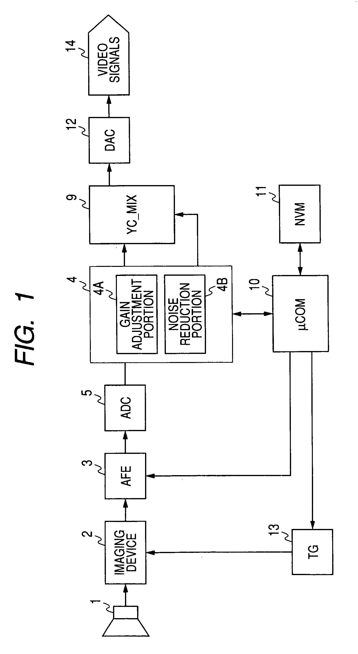
[0065]FIG. 1 is a block diagram of a camera device incorporating an imaging signal-processing circuit associated with the present embodiment of the invention. The camera device corresponds to one form of the “video input processor” of the invention. The camera device can be either a video camera chiefly designed to take motion picture sequences or a digital still camera chiefly designed to take still images.

[0066]The illustrated camera device has optical components 1 including lenses and an optical filter, an imaging device 2, an analog front-end (AFE) circuit 3 for processing an analog imaging signal, an analog-to-digital converter (ADC) 5 for converting the analog imaging signal into a digital signal and outputting the digital signal to various signal-processing portions as a digital video signal, and a digital-to-analog converter (DAC) 12 for converting video signals processed variously into analog signals and outputting the analog signals as video signals 14.

[0067]The optical fi...

second embodiment

[0106]A more detailed embodiment including the noise reduction processing portion 54A that is one feature of the embodiment is described below. It is assumed here that the camera device has the imaging device 2 of the single panel type.

[Configuration of Signal-Processing Portion]

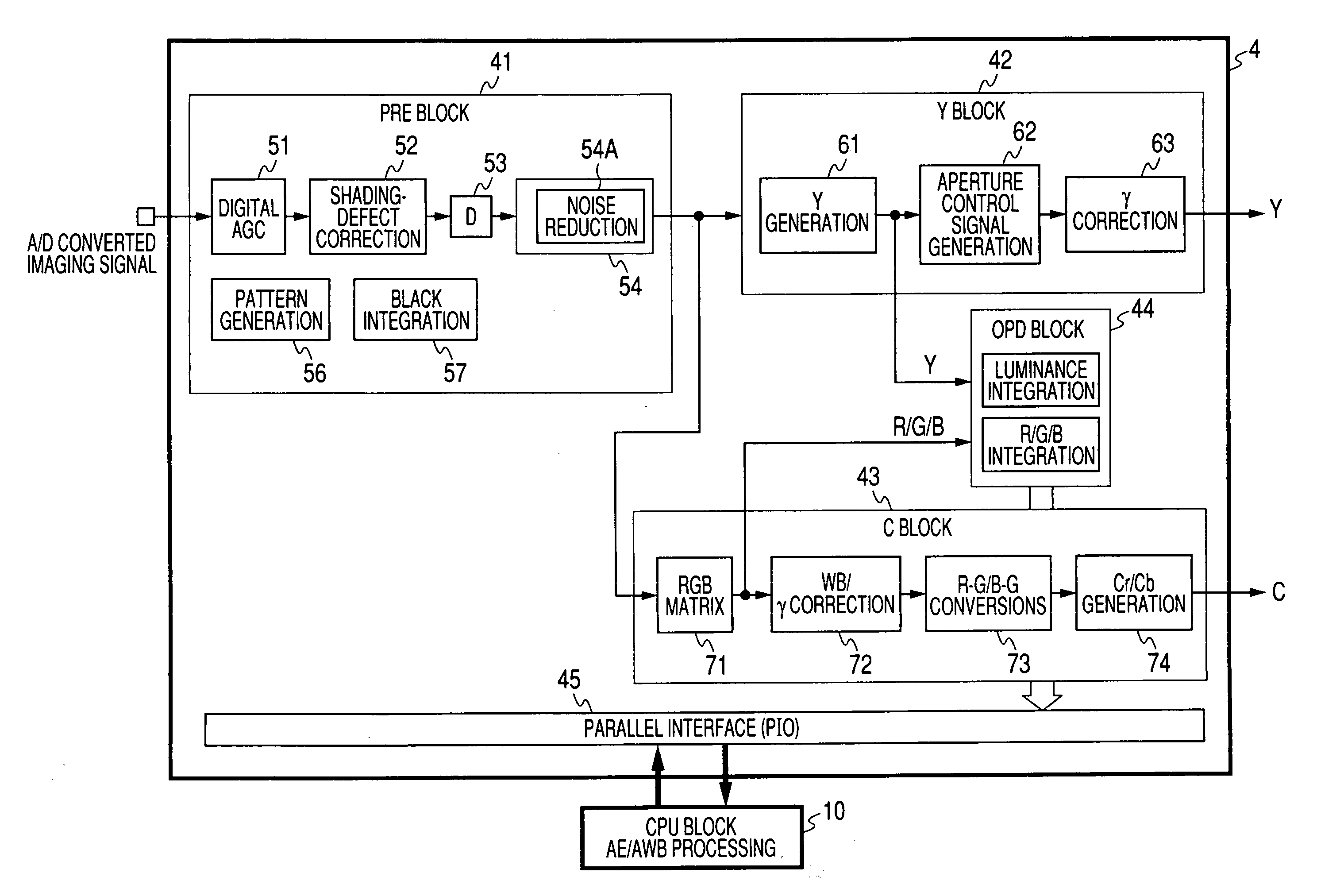
[0107]FIG. 5 is a block diagram showing one example of configuration of the signal-processing portion 4. The illustrated signal-processing portion 4 is made up of some major blocks, i.e., a PRE block 41 for performing preprocessing, a Y block 42 for extracting and processing the luminance signal (Y), a C block 43 for extracting and processing the color signal (C), and an OPD (optical detector) block 44 for detecting the brightness of the image on the display screen. Each block is connected with the microcomputer 10 (CPU block in FIG. 5) via a parallel interface (PIO) 45. The blocks are under control of the microcomputer 10. Thus, processing in the PRE block, automatic exposure (AE), automatic white balance a...


PUM


Abstract

A video input processor is disclosed. The processor includes: an imaging signal-generating portion configured to image a subject and producing first imaging signals containing visible light components and a second imaging signal containing near-infrared light components; a gain adjustment portion configured to adjustably set a maximum gain value according to a relative magnitude between the visible light components and the near-infrared light components and adjust a gain for the first imaging signals at the set maximum gain value; and a noise reduction portion configured to reduce noises in the first imaging signals after the gain has been adjusted.

Description

CROSS REFERENCES TO RELATED APPLICATIONS[0001]The present invention contains subject matter related to Japanese Patent Application JP2007-131557 filed in the Japanese Patent Office on May 17, 2007, the entire contents of which being incorporated herein by reference.BACKGROUND OF THE INVENTION[0002]1. Field of the Invention[0003]The present invention relates to a video input processor for imaging a subject and suppressing noise components of produced imaging signals by signal processing. The invention also relates to an imaging signal-processing circuit and to a method of reducing noises in the imaging signals.[0004]2. Description of the Related Art[0005]When a subject is imaged by a camera device designed to image a motion picture sequence or still images, for example, with enhanced ISO sensitivity, the automatic exposure function is activated. This shortens the exposure time of the sensor (imaging device) and increases the gain for the output signal from the sensor. Therefore, the ...

Claims


Application Information

Patent Timeline
Patent Type & Authority Applications(United States)
IPC IPC(8): H04N5/217H04N9/07
CPCH04N5/217H04N5/23232H04N5/2351H04N5/243H04N5/357H04N9/045H04N23/81H04N23/951H04N23/71H04N23/76H04N25/60H04N23/84H04N25/133H04N25/135H04N23/00
Inventor NUMATA, HAJIME
Owner SONY CORP
Why Eureka
Try Eureka