Data Acquisition System and Method for Mass Spectrometry

a mass spectrometry and data acquisition technology, applied in chemical methods analysis, particle separator tubes, instruments, etc., can solve the problems of difficult to keep track of the gain in order to maintain linearity, fast change of gain on the detector, and inability to maintain linearity. linearity, complex detection solutions,

Active Publication Date: 2013-10-10
THERMO FISHER SCI BREMEN
View PDF15 Cites 55 Cited by
  • Summary
  • Abstract
  • Description
  • Claims
  • Application Information

AI Technical Summary

Benefits of technology

[0078]The data processing system comprises at least one data processing device, which may comprise any suitable data processing device or devices. The data processing system preferably comprises at least one dedicated processing device, especially for fast processing of the detection signals from the detection system on-the-fly. A dedicated processing device is typically only required and/or used for the time critical steps, which are the steps up to and optionally including the data packing step. Preferably, the at least one dedicated processor is designed to do at least decimation and noise filtering using the threshold. Subsequent steps may be performed effectively at any time, including off-line (unless information is required for data dependent acquisition decisions in the system). A dedicated processing device of the data processing system is especially a fast processing device having two or more channels for performing parallel computations therein. The main characteristic of the dedicated processing device is that it has to be able to perform the required computation steps at the required (decimated) data rate. Preferred examples of such fast dedicated processing devices include the following: a d

Problems solved by technology

The problem with the latter detection is that it requires fast change of gain on the detector and it is also difficult to keep track of the gain in order to maintain linearity.
In all, these detection solutions can be complicated and costly to implement and/or their sensitivity and/or their dynamic range can be lower than desired.
Another prob

Method used


Image

  • Data Acquisition System and Method for Mass Spectrometry
  • Data Acquisition System and Method for Mass Spectrometry
  • Data Acquisition System and Method for Mass Spectrometry

Examples


Embodiment Construction

[0103]In order to more fully understand the invention, various non-limiting examples of the invention will now be described with reference to the accompanying Figures in which:

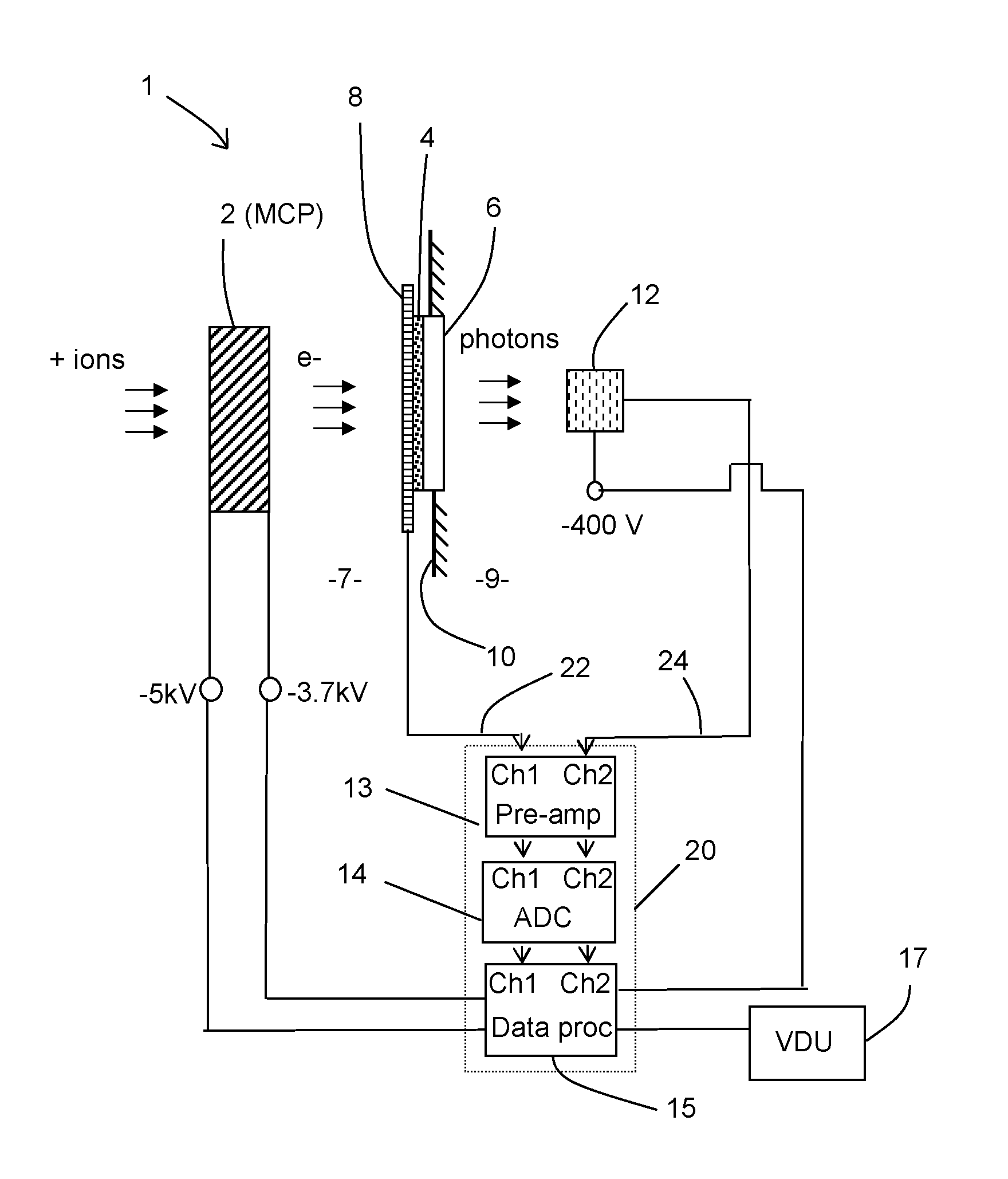
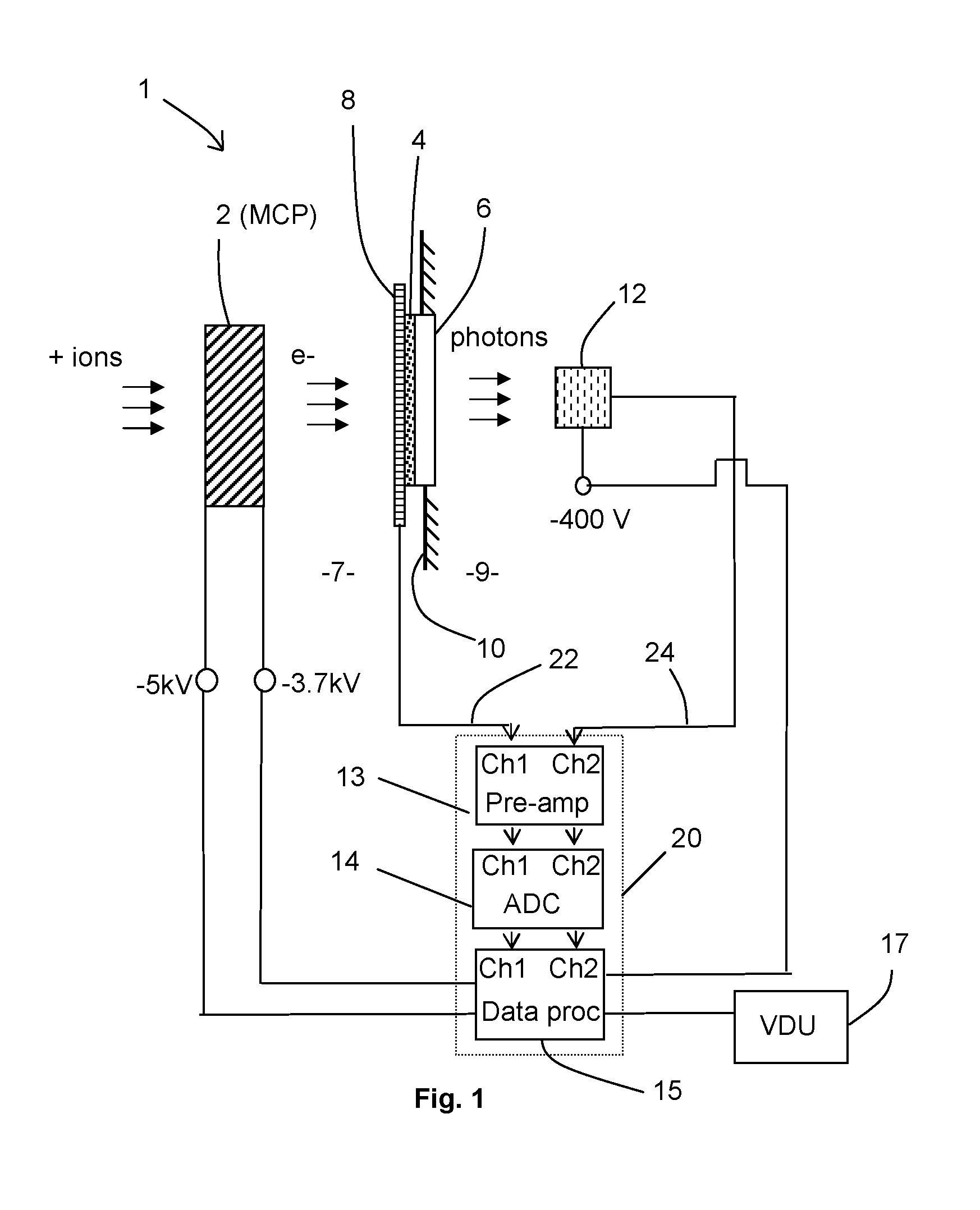
[0104]FIG. 1 shows schematically an embodiment of a detection system forming a part of a data acquisition system according to the present invention;

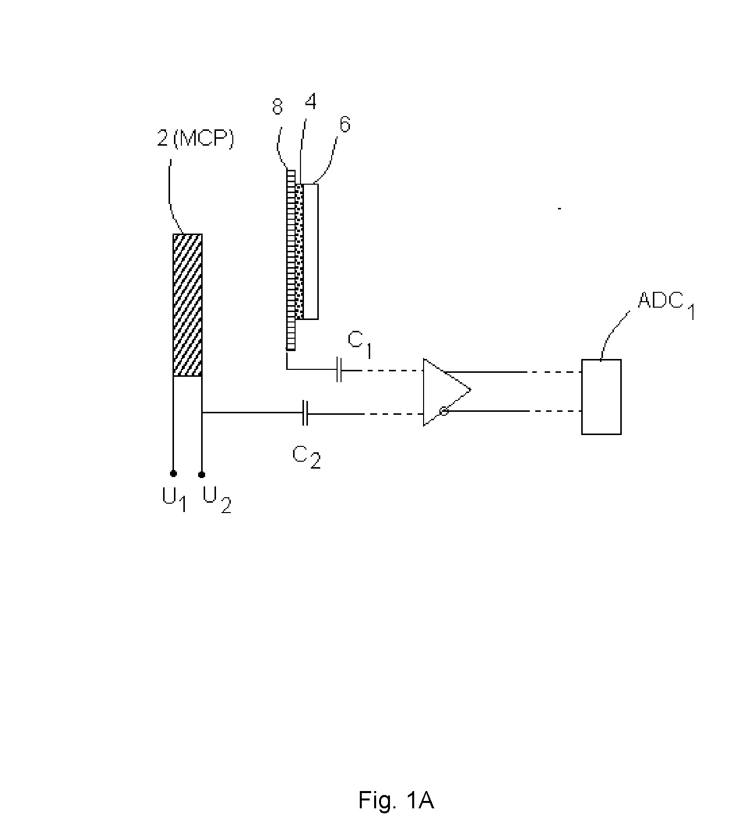
[0105]FIG. 1A shows schematically an embodiment of differential signal detection in a first detection channel;

[0106]FIG. 1B shows schematically an embodiment of differential signal detection in a second detection channel;

[0107]FIG. 2 shows a schematic representation of an embodiment of the present invention, including examples of data processing steps;

[0108]FIG. 3A shows a schematic flow chart of a preferred sequence of steps performed by the threshold calculator 90 of FIG. 2;

[0109]FIG. 3B shows a window on a detection signal used for determining a noise threshold and the position of the threshold;

[0110]FIG. 3C shows a section of a detection signal and a plurality ...


PUM


Abstract

The invention provides a data acquisition system and method for detecting ions in a mass spectrometer, comprising: a detection system for detecting ions comprising two or more detectors for outputting two or more detection signals in separate channels in response to ions arriving at the detection system; and a data processing system for receiving and processing the detection signals in separate channels of the data processing system and for merging the processed detection signals to construct a mass spectrum; wherein the processing in separate channels comprises removing noise from the detection signals by applying a threshold to the detection signals. The detection signals are preferably produced in response to the same ions, the signals being shifted in time relative to each other. The invention is suitable for a TOF mass spectrometer.

Description

FIELD OF THE INVENTION[0001]This invention relates to data acquisition systems and methods for detecting ions in a mass spectrometer and improvements in and relating thereto. The systems and methods are useful for a mass spectrometer, preferably a time-of-flight (TOF) mass spectrometer and thus the invention further relates to mass spectrometers and methods of mass spectrometry incorporating the data acquisition systems and data acquisition methods. The invention may be used for the production of high dynamic range and high resolution mass spectra and these spectra may be used for the identification and / or quantification of organic compounds, e.g. active pharmacological ingredients, metabolites, small peptides and / or proteins.BACKGROUND OF THE INVENTION[0002]Mass spectrometers are widely used to separate and analyse ions on the basis of their mass to charge ratio (m / z) and many different types of mass spectrometer are known. Whilst the present invention has been designed with Time-o...

Claims


Application Information

Patent Timeline
IPC IPC(8): H01J49/02
CPCH01J49/025H01J49/0036
Inventor MAKAROV, ALEXANDER A.GIANNAKOPULOS, ANASTASSIOSBIEL, MATTHIAS
Owner THERMO FISHER SCI BREMEN
Why Eureka
Try Eureka