The
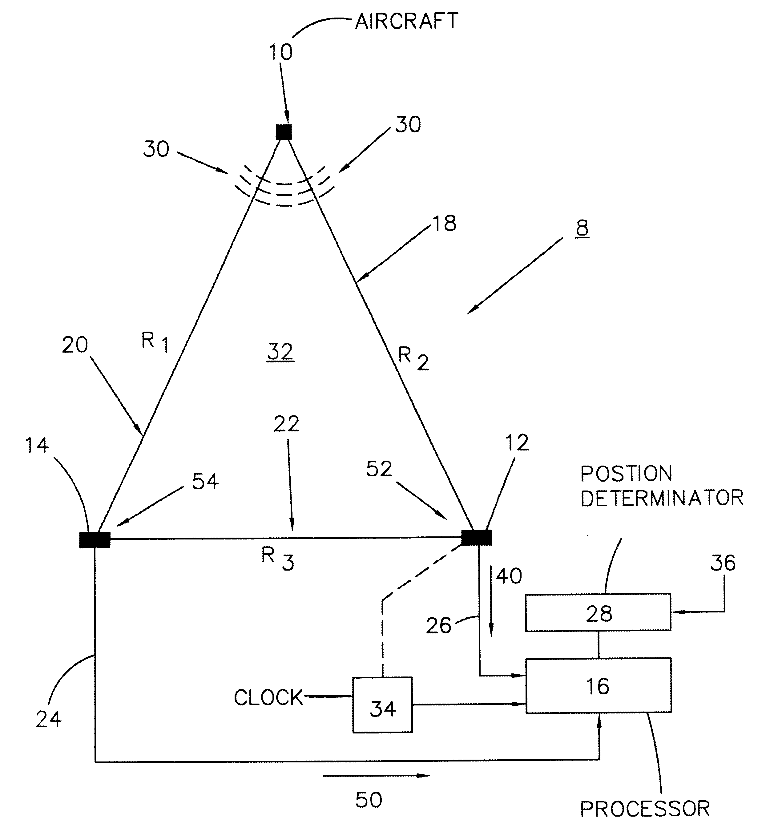
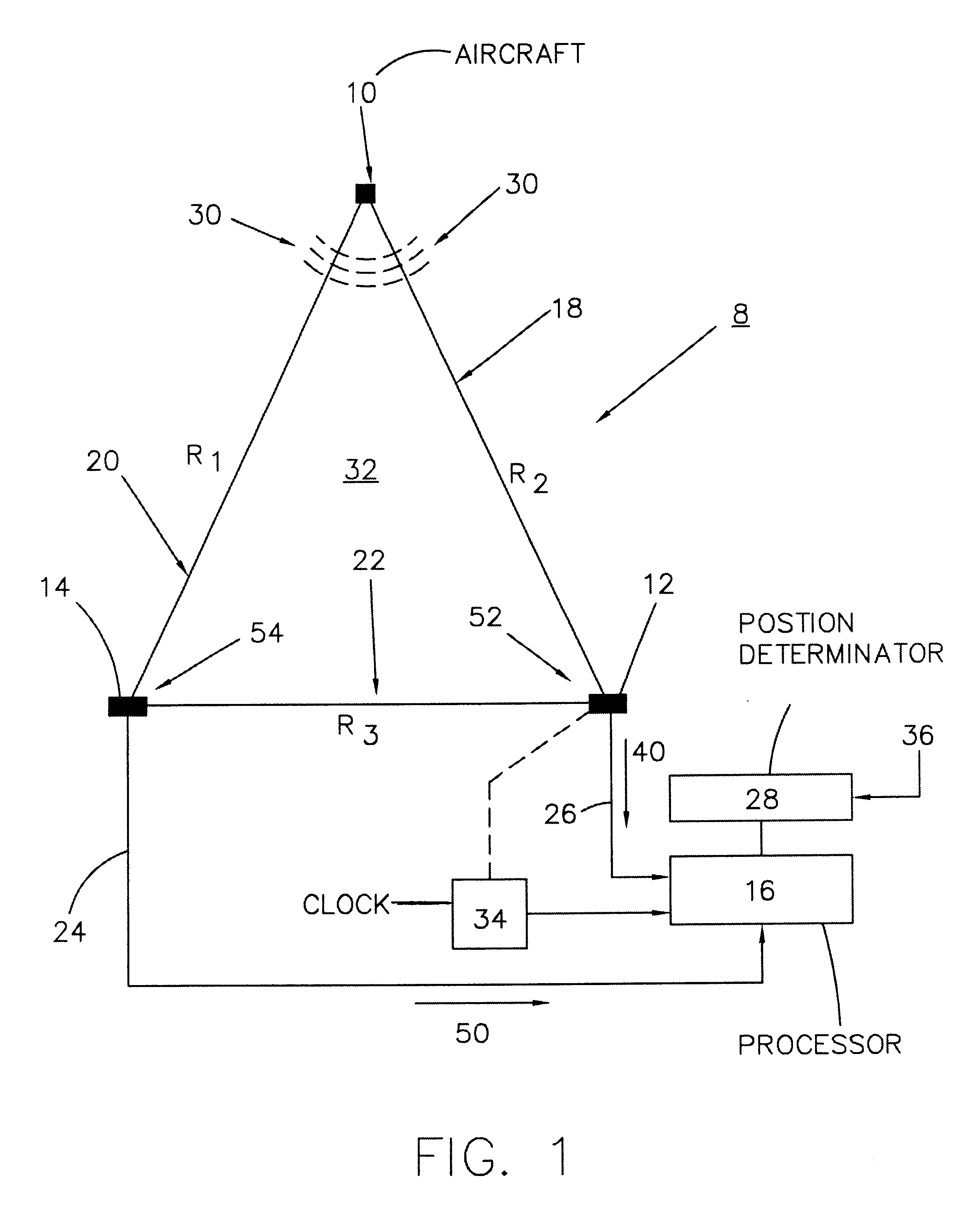
system 8 may also include a
clock, or
local oscillator 34. The
clock 34 may be used to time stamp the first signal 40 from the first antenna 12 and the second signal 50 from the second antenna 14. In an alternate embodiment, any suitable means to provide a time reference for first signal 40 and second signal 50 may be used, including, other than the
clock 34. In the preferred embodiment, the clock 34 is a ground
crystal clock, however, any suitable clock may be used. Preferably, clock 34 is common to the components of
system 8, including antennas 12,and 14, processor 16 and position determinator 28. In alternate embodiments, separate clocks may be used to time stamp the first and second signals 40, 50. It is a feature of the present invention to substitute high TDOA
signal processing gain for
antenna gain. This eliminates the need for more than one specialized
high gain antenna. However, the generation of high TDOA
processing gain typically requires two or more highly stabilized clocks, typically atomic clocks, local to each antenna receiver. These two clocks are required to sample and accurately time stamp respective received signals for high processing gain TDOA correlation calculations. However, relative
clock drift prevents correlating long blocks of data for high
signal processing gain. The separate atomic clocks at each site are used to reduce
clock drift. It is a feature of the present invention to use a common clock to sample and time stamp received signals in order to eliminate relative
clock drift. The use of a common clock for the components of system 8 provides signals time stamped to a common reference which provides higher
signal processing gain in the processor 16. This unique feature allows the second antenna 14 to be a
low gain, omni-
directional antenna.
The connections between and among the first antenna 12, the second antenna 14, the processor 16 and the position determinator 28 are preferably made using
fiber optic links or cables. However, in an alternate embodiment, any suitable type of link or connection could be provided between or among the antennas 12, 14, the processor 16 and the position determinator 28. The use of a
coaxial cable, wave guide or
fiber optic cable is needed in order to contain the received signals and prevent local interference of the receive antennas 12, 14 in the event the signals are re-radiated or transmitted in
free space, to the TDOA signal processor 16. It is a feature of the present invention to use a
fiber optic RF cable to connect the receiver terminals of the system 8 to an inexpensive common clock in the TDOA processor in order to allow a large baseline (R3) distance between the first antenna 12 and the second antenna 14. In the preferred embodiment, this baseline distance can exceed 1000 feet (304.80 meters). It is difficult to use RF coaxial cables in order to bring RF signals together over long distances. In RF coax, coaxial attenuation of 500 dB per kilometer prevents a baseline separation of more than about 100 feet (30.48 meters). Wave-guides are very expensive. The use of secondary
free space RF links would interfere with the existing receivers.
Fiber optic RF links are generally inexpensive and typically can have attenuation of only about 0.5 dB per kilometer. This allows antenna terminal baseline separations of more than 1000 feet (304.80 meters). It is a feature of the present invention to use a fiber optic RF link to bring together two or more RF signals spaced by a baseline distance of in excess of 1000 feet (304.80 meters) and process the signals with an inexpensive common
crystal clock. These features of the present invention produce high TDOA signal processing gain that can be substituted for antenna
signal gain. Consequently, the use of atomic clocks and a
high gain antenna can be eliminated in accurately determining the TDOA location of an aircraft.
The system of the present invention can be used to accurately determine the position of the aircraft 10. The method generally comprises positioning a first antenna 12 a spaced baseline distance from a second antenna 14.
In the preferred embodiment, the baseline distance is known and can exceed 1000 feet (304.80 meters). However, in an alternate embodiment, the baseline distance can be any suitable distance other than including a distance more than 1000 feet (304.80 meters). For example, a distance of less than 1000 feet (304.80 meters) could be used. A larger baseline distance can be used to improve, or achieve a high position accuracy of the aircraft with the TDOA calculations.
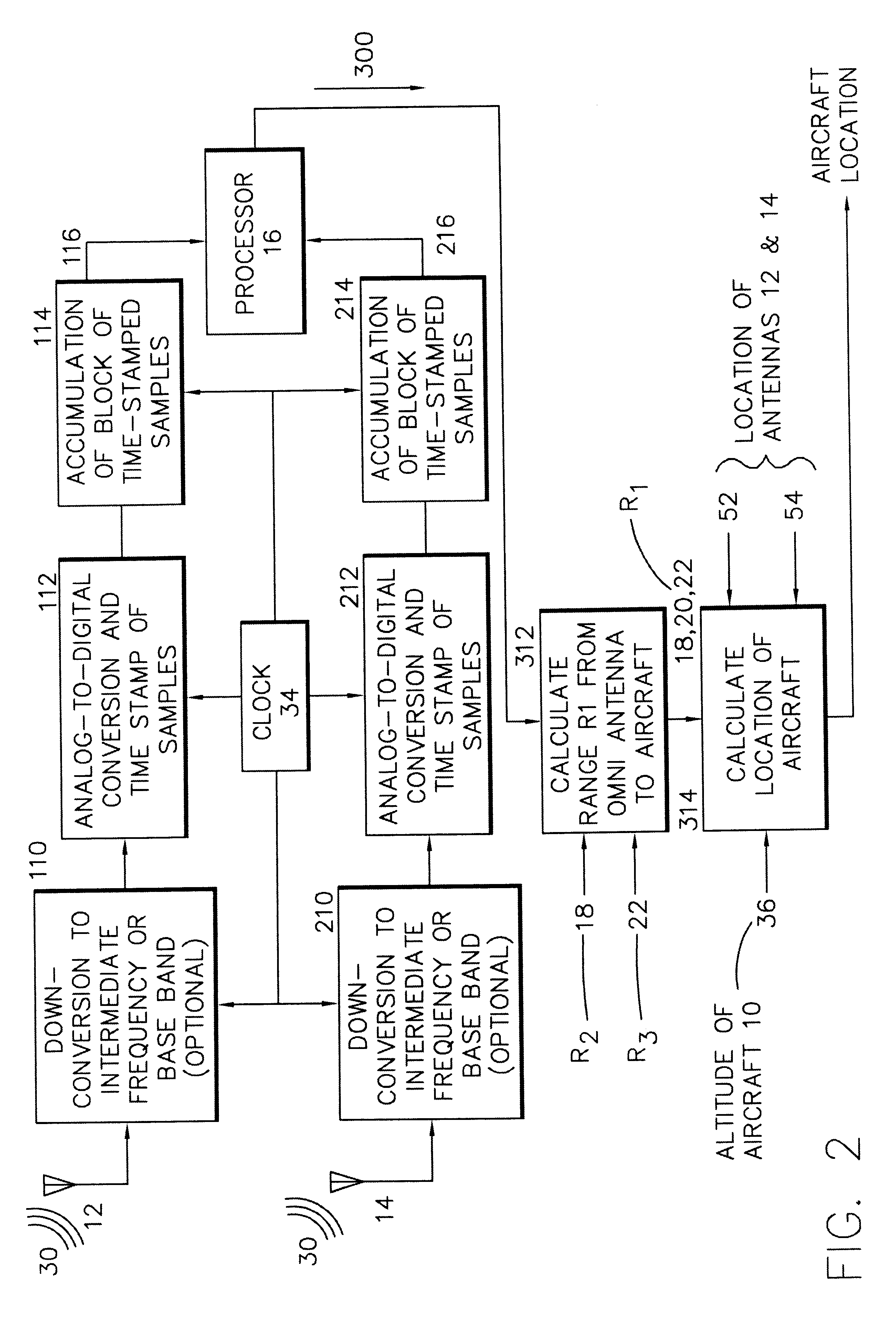
Typically, the aircraft signal 30 is received at the first antenna 12 and the second antenna 14. Each antenna may include processing hardware adapted to processes the received signal by digitizing and
time stamping the received signal. The first antenna 12 and the second antenna 14 will typically generate the first signal 40 and the second signal 50 respectively. In the preferred embodiment, signals 40, 50 will be time stamped with the clock 34. However, in an alternate embodiment, any suitable means of providing a time reference for signals 40, 50, may be used, including other than the clock 34. One of the features of the present invention is that the use of a common clock to time stamp the first and second signals 40, 50, results in long blocks of digitized signals in the processor 16 during the cross correlation process. A cross-correlation process is typically used to determine the TDOA between signals 40 and 50. High TDOA signal processing gain can be substituted for
antenna gain. The use of a common clock eliminates clock drift and allows the long blocks of data to be correlated for high signal processing gain. These long blocks of digitized signals, or correlated data, result in high signal processing gain of the processor 16 which allows the second antenna 14 to be an inexpensive,
low gain, omni-
directional antenna.
The processor 16 then typically receives the first signal 40 and the second signal 50 and calculates a TDOA between the signals. Typically, the TDOA is measured by sampling the first and second signals 40, 50 and determining the time slippage correlation between the sampled blocks of data. In the preferred embodiment, the first and second signals 40, 50 may be RF, IF or
baseband signals. Down converting RF to some convenient IF frequency for sampling provides a high level of accuracy resolution. Preferably, the sampling rate should be at least two times the bandwidth of the first and second signals 40, 50, although any suitable bandwidth may be used. The sampled
data set is then passed to the processor 16, where the TDOA is determined. Typically, the TDOA is determined using a standard cross correlation process, however, any suitable TDOA calculation process may be used. It is assumed that the first and second signals 40, 50, are not periodic. In a typical cross correlation process, at some time stamp reference, corresponding samples from the two data streams are multiplied and summed. If the correlation is small, the sum will be near zero. Then the first
data set is slipped one sample past the second, and the multiply and sum operations are repeated. This process is repeated until the sum becomes a large positive value, which occurs when corresponding multiplied values are alike. The slip time for the two sets of data to align relative to the time stamp is the TDOA value. In an alternate embodiment, the TDOA may be determined by any conventional time slippage correlation technique including, other than the foregoing cross-correlation procedure. Typically, the processor 16 will function similar to a pseudo
noise ("PN") code receiver with its stored-local-noiseless PN code. As cross correlation proceeds, the signal received from the first antenna 12 will be almost noiseless, as in the PN code case. Consequently, the cross correlation calculation, even with the
low gain, noisy signal received from the second antenna 14, will produce high processing gain when the two received signals match.

