Detection Apparatus for Detecting Charged Particles, Methods for Detecting Charged Particles and Mass Spectrometer

a technology of detection apparatus and charged particles, which is applied in the direction of mass spectrometer, isotope separation, particle separator tubes, etc., can solve the problems of high cost, high cost, and high cost of electronics, and achieves the effect of improving the efficiency of photon generation, reducing the cost of detection, and increasing the kinetic energy of charged particles impinging

Active Publication Date: 2011-04-28
THERMO FISHER SCI BREMEN
View PDF23 Cites 55 Cited by
  • Summary
  • Abstract
  • Description
  • Claims
  • Application Information

AI Technical Summary

Benefits of technology

[0038]According to yet another aspect of the present invention there is provided a method of improving the dynamic range of detection for a TOF mass spectrometer comprising:
[0091]a) Adjusting the gain of the high-gain channel while the intense (or weak) peak is present (i.e. being detected). Reducing the gain for intense peaks may also prolong the life of the photon detector. The data from the reduced-gain high-gain channel can be used during this period or, optionally, data from the charge detector can be used during this period such that there is no need to know how much the gain was reduced;

Problems solved by technology

Complications may arise from the necessary complexity of electronics which this entails, e.g. where the detector is required to float at many keV potential, and the high voltage has an effect on the detector output.
However, such detectors suffer from a relatively poor dynamic range.
The problem with the latter detection is that it requires fast change of gain on the detector and it is also difficult to keep track of the gain in order to maintain linearity.
Methods of combining two detector outputs are disclosed in WO 2009 / 027252 A2, US 2002 / 0175292 and U.S. Pat. No. 6,646,252.In all, these detection solutions can be complicated and costly to implement and / or their sensitivity and / or their dynamic range can be lower than desired.

Method used


Image

  • Detection Apparatus for Detecting Charged Particles, Methods for Detecting Charged Particles and Mass Spectrometer
  • Detection Apparatus for Detecting Charged Particles, Methods for Detecting Charged Particles and Mass Spectrometer
  • Detection Apparatus for Detecting Charged Particles, Methods for Detecting Charged Particles and Mass Spectrometer

Examples


Embodiment Construction

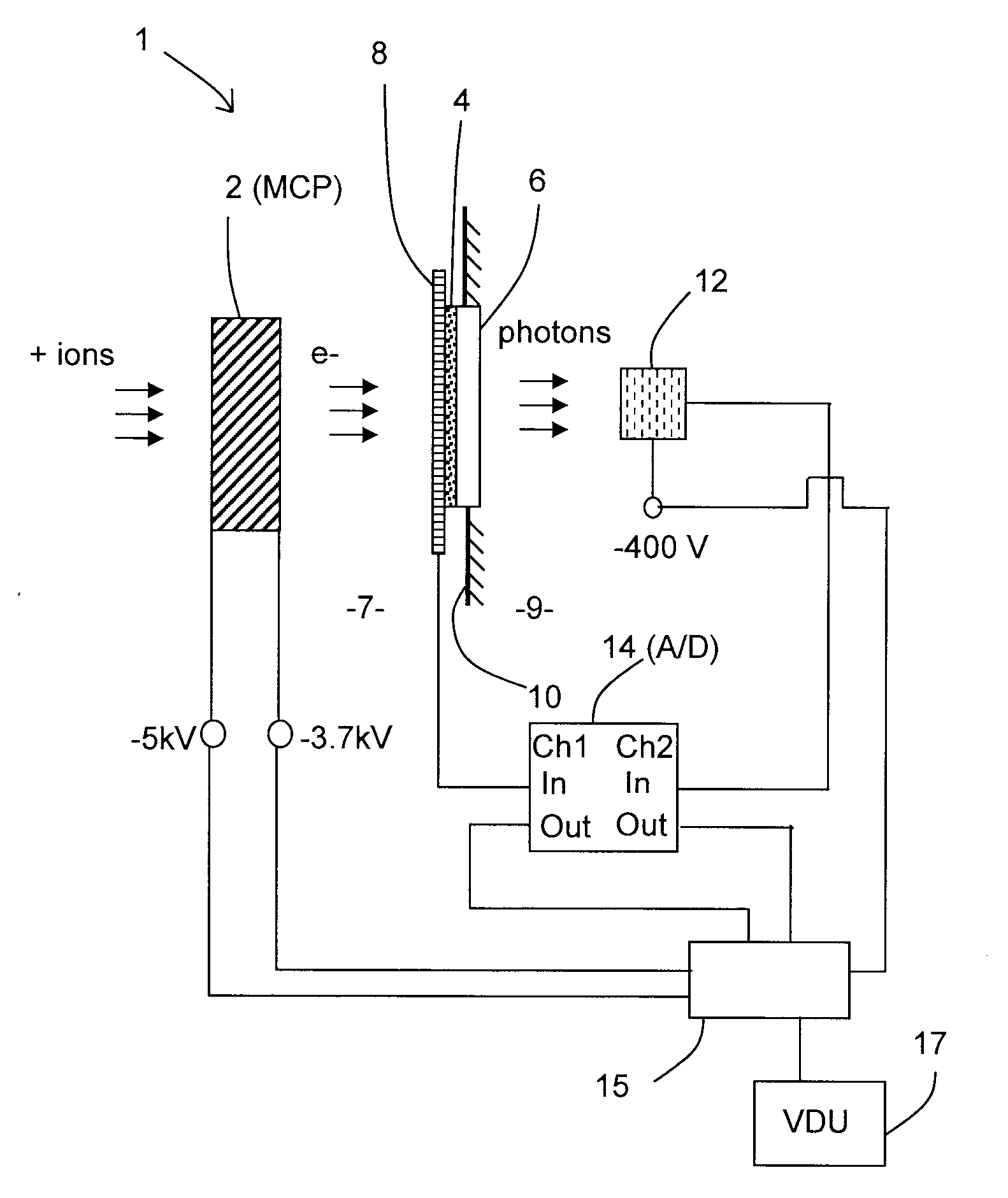
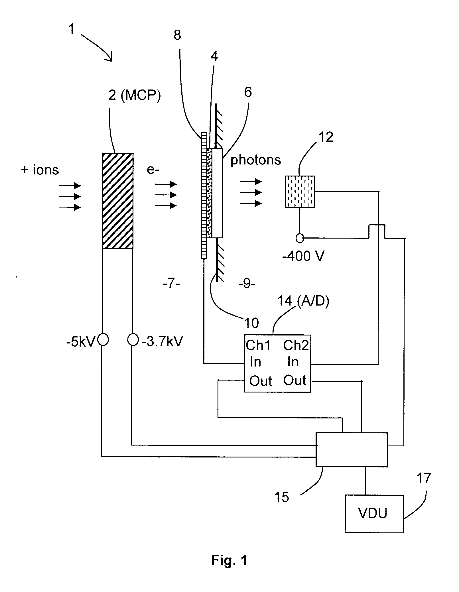
[0124]Referring to FIG. 1 there is shown schematically a first embodiment of an apparatus according to the present invention. The apparatus 1 comprises a micro-channel plate (MCP) 2 to act as a secondary electron generator and generate secondary electrons (e−) from incoming ions (+ ions) which are incident on the MCP 2. The MCP is a Hamamatsu F2222-21 without its usual phosphor screen. The MCP 2 is located in a vacuum environment, e.g. the vacuum environment of a mass spectrometer. The rear of the MCP 2 from which secondary electrons are emitted in operation faces a scintillator in the form of a phosphor screen 4 (model El-Mul E36), which emits photons of nominal wavelength 380 nm in response to electron bombardment. Herein, the terms the front or front side of a component means the side closest to the incoming ions (i.e. the upstream side) and the rear or rear side of the component means the side furthest from the incoming ions (i.e. the downstream side). The phosphor screen 4 is s...


PUM


Abstract

Embodiments of the invention provide a detection apparatus for detecting charged particles having a secondary particle generator for generating secondary charged particles in response to receiving incoming charged particles, a charged particle detector for receiving and detecting secondary charged particles generated by the secondary particle generator, a photon generator for generating photons in response to receiving secondary charged particles generated by the secondary particle generator, and a photon detector for detecting the photons generated by the photon generator.

Description

FIELD OF THE INVENTION [0001]This invention relates to detection apparatus for detecting charged particles, methods for detecting charged particles and improvements in and relating thereto. The apparatus and method are useful for a mass spectrometer or the like and thus the invention further relates to a mass spectrometer.BACKGROUND [0002]Charged particle detectors are used in many applications requiring, for example, ion or electron detection. One such application is mass spectrometry. Mass spectrometers are widely used to separate and analyse charged particles on the basis of their mass to charge ratio (m / z) and many different types of mass spectrometer are known. Whilst the present invention has been designed with Time-of-flight (TOF) mass spectrometry in mind, the invention is applicable to other types of mass spectrometry as well as applications other than mass spectrometry which require the detection of charged particles, e.g. electron microscopy.[0003]Time-of-flight (TOF) mas...

Claims


Application Information

Patent Timeline
Patent Type & Authority Applications(United States)
IPC IPC(8): H01J49/00
CPCH01J49/025H01J49/40H01J2237/2444
Inventor GIANNAKOPULOS, ANASTASSIOSMAKAROV, ALEXANDER A.
Owner THERMO FISHER SCI BREMEN
Why Eureka
Try Eureka