
Adaptive impedance matching apparatus, system and method with improved dynamic range

a technology of impedance matching and dynamic range, applied in waveguide type devices, antenna details, antennas, etc., can solve the problems of limited dynamic range of about 25 db, high cost, chip area, and high current drain, so as to improve the linearity of the module, improve the dynamic range of the apparatus, and improve the effect of signal level

Active Publication Date: 2010-12-14
NXP USA INC
View PDF138 Cites 132 Cited by
  • Summary
  • Abstract
  • Description
  • Claims
  • Application Information

AI Technical Summary

Benefits of technology

The solution significantly improves the dynamic range of RF power transfer, achieving up to 61.6 dB and enhancing linearity, particularly at high signal levels, while reducing costs and complexity compared to existing technologies.

Problems solved by technology

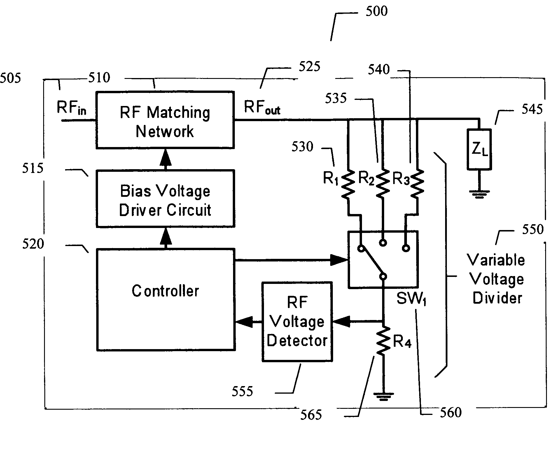
The lowest cost RF voltage detector is a simple diode detector, but it has a limited dynamic range of about 25 dB.
Logarithmic amplifiers (that detect the signal envelope) have a much higher dynamic range of 50 dB to 60 dB, but their cost, complexity, chip area, and current drain is also much higher.

Method used


Image

  • Adaptive impedance matching apparatus, system and method with improved dynamic range
  • Adaptive impedance matching apparatus, system and method with improved dynamic range
  • Adaptive impedance matching apparatus, system and method with improved dynamic range

Examples


Embodiment Construction

[0015]In the following detailed description, numerous specific details are set forth in order to provide a thorough understanding of the invention. However, it will be understood by those skilled in the art that the present invention may be practiced without these specific details. In other instances, well-known methods, procedures, components and circuits have not been described in detail so as not to obscure the present invention.

[0016]Some portions of the detailed description that follows are presented in terms of algorithms and symbolic representations of operations on data bits or binary digital signals within a computer memory. These algorithmic descriptions and representations may be the techniques used by those skilled in the data processing arts to convey the substance of their work to others skilled in the art.

[0017]An algorithm is here, and generally, considered to be a self-consistent sequence of acts or operations leading to a desired result. These include physical mani...


PUM


Abstract

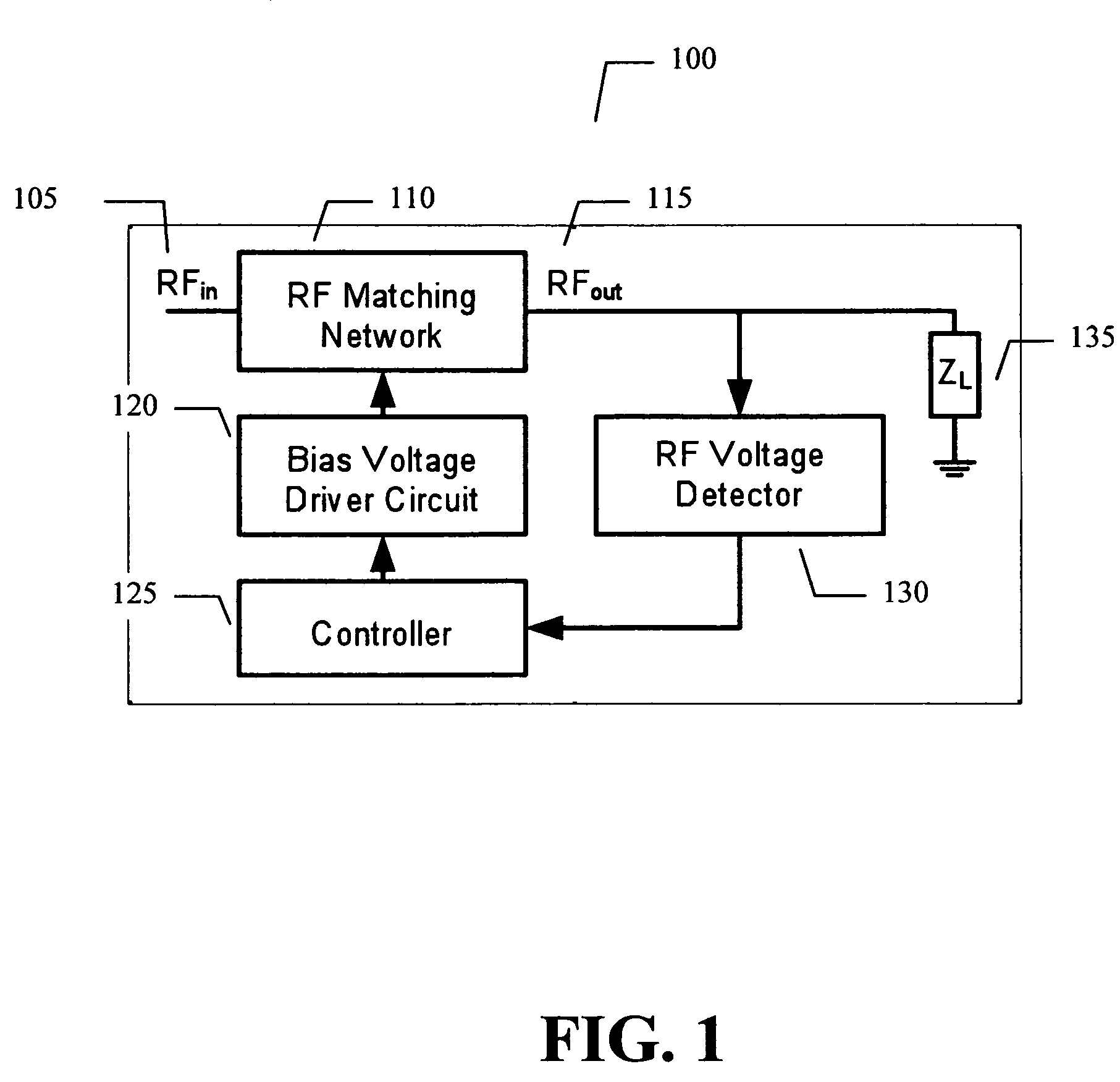
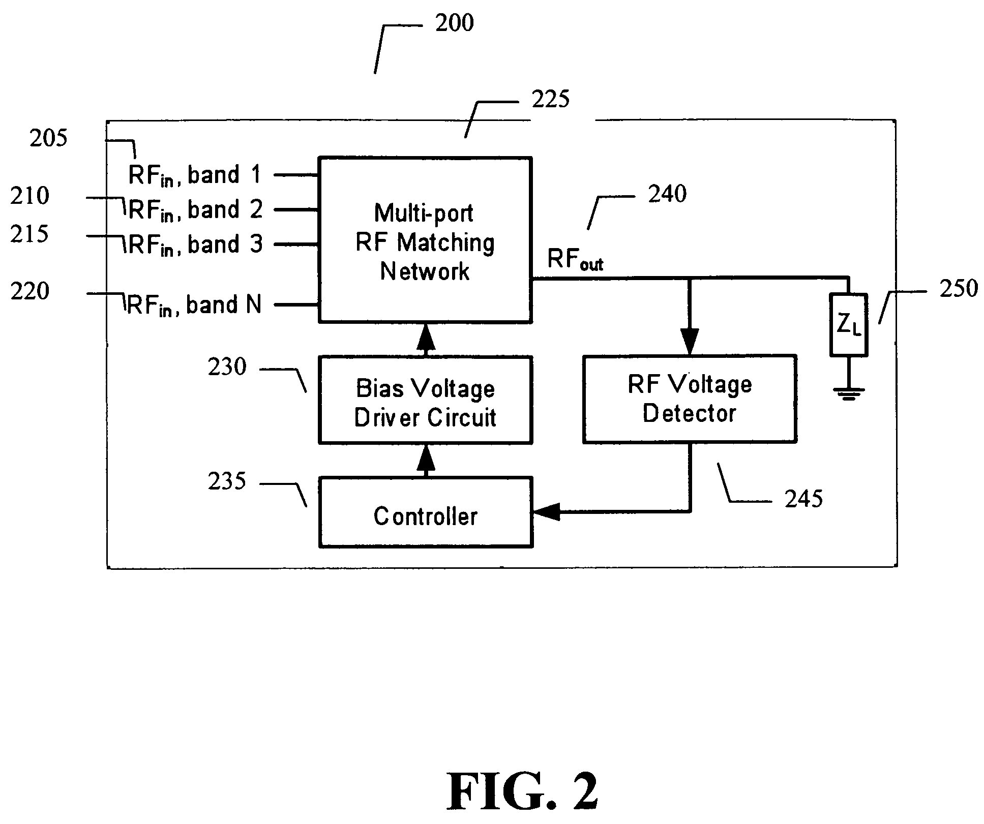
An embodiment of the present invention provides an apparatus, comprising an RF matching network connected to at least one RF input port and at least one RF output port and including one or more voltage or current controlled variable reactive elements; a voltage detector connected to the at least one RF output port via a variable voltage divider to determine the voltage at the at least one RF output port and provide voltage information to a controller that controls a bias driving circuit which provides voltage or current bias to the RF matching network; a variable voltage divider connected to the voltage detector and implemented using a multi-pole RF switch to select one of a plurality of different resistance ratios to improve the dynamic range of the apparatus; and wherein the RF matching network is adapted to maximize RF power transferred from the at least one RF input port to the at least one RF output port by varying the voltage or current to the voltage or current controlled variable reactive elements to maximize the RF voltage at the at least one RF output port.

Description

CROSS REFERENCE TO RELATED PATENT APPLICATION[0001]This application is a divisional of U.S. patent application Ser. No. 11 / 594,309, filed Nov. 8, 2006 now U.S. Pat. No. 7,535,312, entitled, ADAPTIVE IMPEDANCE MATCHING APPARATUS, SYSTEM AND METHOD WITH IMPROVED DYNAMIC RANGE, by William E. McKinzie.BACKGROUND[0002]The function of an adaptive impedance matching module is to adaptively maximize the RF power transfer from its input port to an arbitrary load impedance ZL that changes as a function of time.[0003]One of the important engineering specifications of an impedance matching control system is the dynamic range of input power over which it will operate. The lowest cost RF voltage detector is a simple diode detector, but it has a limited dynamic range of about 25 dB. Logarithmic amplifiers (that detect the signal envelope) have a much higher dynamic range of 50 dB to 60 dB, but their cost, complexity, chip area, and current drain is also much higher. Thus, a strong need exists for ...

Claims


Application Information

Patent Timeline
Patent Type & Authority Patents(United States)
IPC IPC(8): H03H7/38H04B1/04
CPCH03H7/40H01Q1/50H04B1/0458H03H2007/386H01Q1/243
Inventor MCKINZIE, III, WILLIAM E.
Owner NXP USA INC
Learn More