Optical sensor device for detecting wetting

a sensor device and optical sensor technology, applied in vehicle maintenance, vehicle cleaning, instruments, etc., can solve the problems of large packaging space required for this device, large yield of usable light, and high susceptibility to extraneous light, so as to save space, small thickness, and large sensor area of the window can be scanned.

Inactive Publication Date: 2010-07-06
TRW AUTOMOTIVE ELECTRONICS & COMPONENTS GMBH & CO KG
View PDF21 Cites 141 Cited by
  • Summary
  • Abstract
  • Description
  • Claims
  • Application Information

AI Technical Summary

Benefits of technology

[0006]According to the invention an optical sensor device comprises a sensor unit which includes an emitter, a receiver and a light conductor unit. The light conductor unit is configured such that a light beam emitted by the emitter is coupled into the window, coupled out of the window and directed onto the receiver. The light conductor unit includes Fresnel lens regions and reflecting regions associated to the Fresnel lens regions. As compared to classical lenses, the light conductor unit with the Fresnel lens regions in accordance with the invention can be designed with a smaller thickness. In addition, the light conductor unit can be arranged parallel to the window so as to save space, because it enables coupling the light beam into and out of the window at an angle. The invention is based on the finding that when a light beam aligned in parallel is suitably coupled into the window at an angle, a relatively large sensor area of the window can be scanned. In addition, the Fresnel lens regions with the associated reflecting regions in accordance with the invention provide for an even more compact design of the light conductor unit.

Problems solved by technology

These sensors are based on the principle of light diffraction by means of defractive elements and therefore have the principal disadvantage of a substantially smaller yield of usable light and a higher susceptibility to extraneous light.
Nevertheless, the packaging space required for this device is very large due to the complex light conductor unit, which necessitates an arrangement of the circuit board carrying emitter and receiver vertical to the windscreen.

Method used


Image

  • Optical sensor device for detecting wetting
  • Optical sensor device for detecting wetting
  • Optical sensor device for detecting wetting

Examples


Embodiment Construction

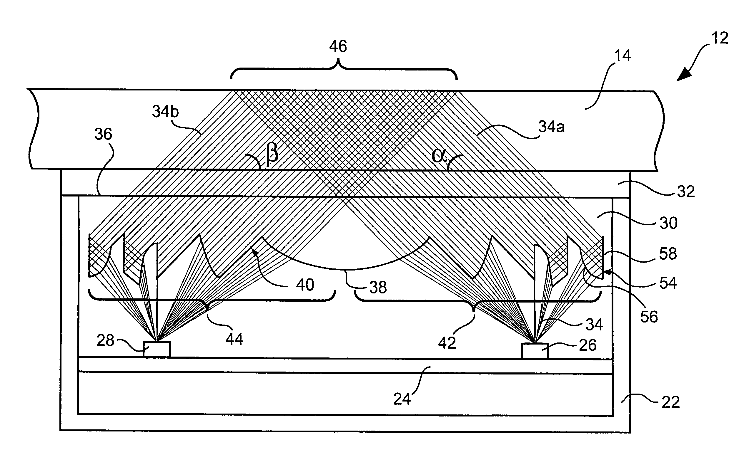
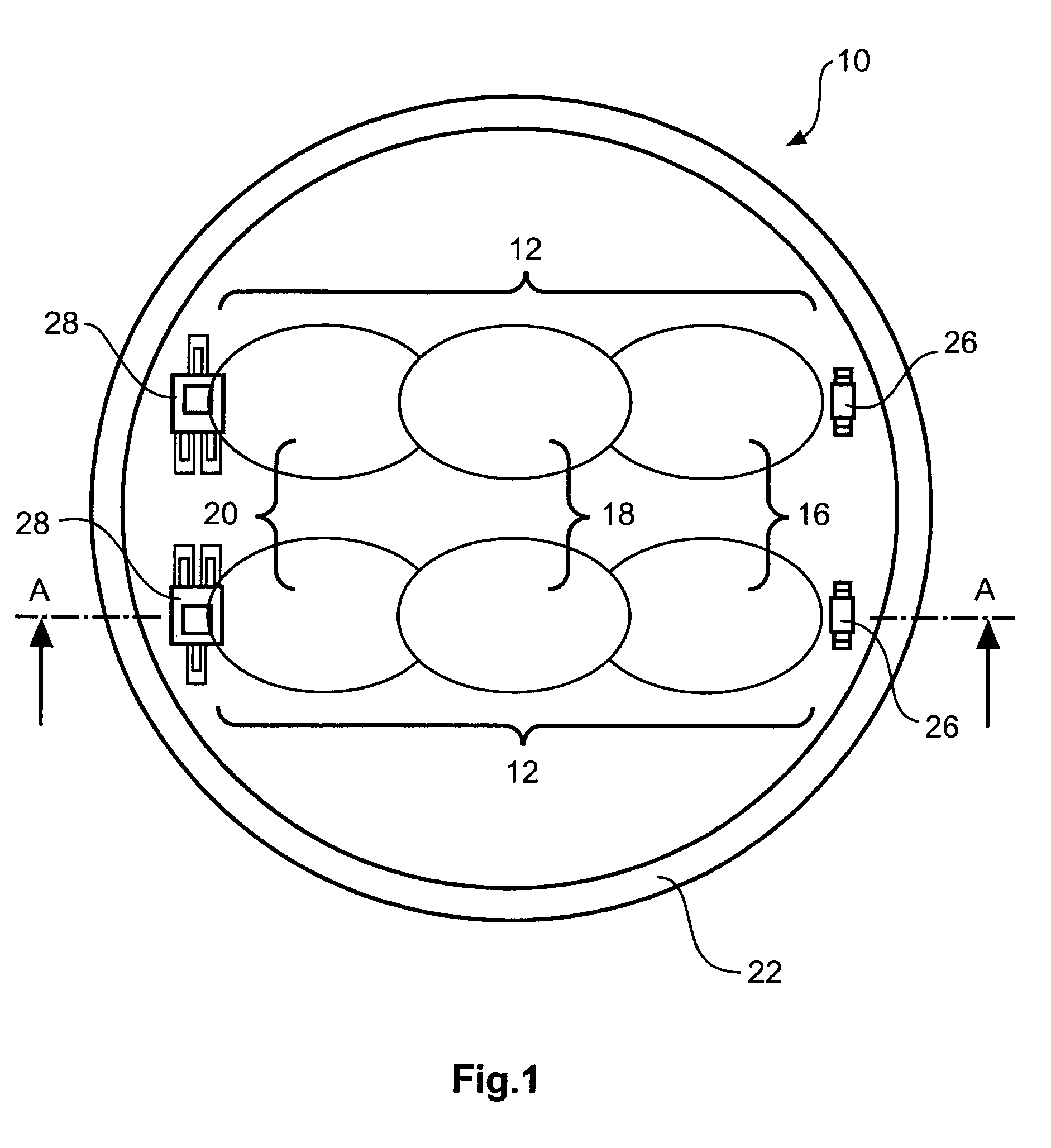
[0011]FIG. 1 shows an optical sensor device 10 according to the invention with two identical sensor units 12 for detecting the wetting of a window. In the following, the sensor device 10 will be described for use as a rain sensor which is mounted on the windscreen 14 (see FIG. 2) of a motor vehicle. In the illustration of FIG. 1, a few components of the sensor device 10 are omitted, in order to emphasize the light impingement surfaces 16, 18, 20 described in detail below.

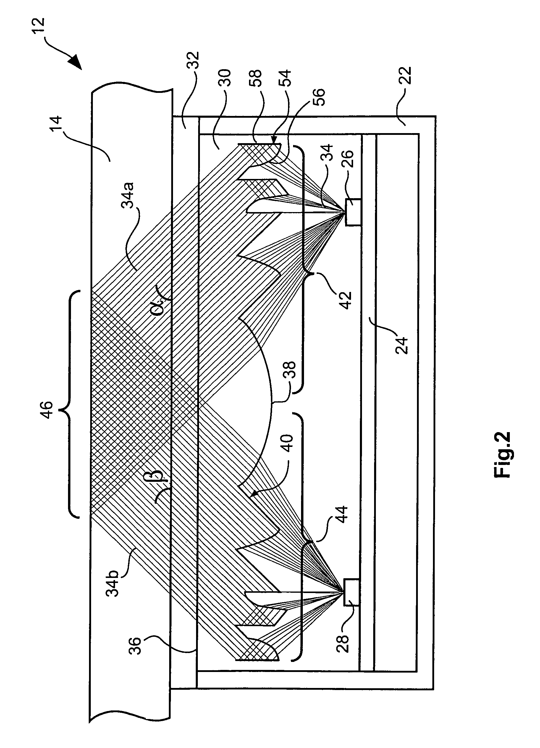
[0012]The basic configuration of the sensor units 12 is illustrated in the sectional illustration of FIG. 2. In a housing 22, which is open on one side, a circuit board 24 with a emitter 26 and a receiver 28 for each sensor unit 12 is accommodated. In the mounted condition of the sensor device 10, i.e. when the sensor device 10 is mounted on a windscreen 14, the windscreen 14 and the circuit board 24 are aligned substantially parallel to each other. Between the circuit board 24 and the windscreen 14 a light conducto...


PUM

PropertyMeasurementUnit
angleaaaaaaaaaa
angle of incidenceaaaaaaaaaa
emergence angleaaaaaaaaaa

Abstract

An optical sensor device (10) is able to be coupled to a window (14), in particular to a windscreen of a motor vehicle. The optical sensor device (10) comprises a sensor unit (12), which includes a emitter (26), a receiver (28) and a light conductor unit (30). By the light conductor unit (30), a light beam (34) emitted by the emitter (26) is coupled into the window (14), coupled out of the window (14) and directed onto the receiver (28). The light conductor unit (30) includes Fresnel lens regions and associated reflecting regions.

Description

TECHNICAL FIELD[0001]This invention relates to an optical sensor device which can be coupled to a window, in particular to a windscreen of a motor vehicle.BACKGROUND OF THE INVENTION[0002]Such sensor devices comprising a sensor unit which includes a emitter, a receiver and a light conductor unit by which a light beam emitted by the emitter is coupled into the window, coupled out of the window and directed onto the receiver, are chiefly used as rain sensors in motor vehicles for automatically actuating the wipers. The use of classical lenses for influencing the optical path, such as the lenses of the rain sensor disclosed in European patent EP 1 068 112 B1, which are inclined against the windscreen, requires a relatively large packaging space.[0003]As known for instance from international application WO 03 / 026937 A1, smaller constructions are possible by using holographic sensors. These sensors are based on the principle of light diffraction by means of defractive elements and theref...

Claims


Application Information

Patent Timeline
Patent Type & Authority Patents(United States)
IPC IPC(8): G01N21/55
CPCB60S1/0822B60S1/0837
Inventor BACKES, ULRICH
Owner TRW AUTOMOTIVE ELECTRONICS & COMPONENTS GMBH & CO KG
Why Eureka
Try Eureka