
Golf club head

a golf club and head technology, applied in the field of golf club head, can solve the problems of insufficient initial launch speed of the ball, inability to obtain sufficient launch angle with a head deformable, and increase the extra weight of the head

Inactive Publication Date: 2004-08-31
BRIDGESTONE SPORTS
View PDF10 Cites 97 Cited by
  • Summary
  • Abstract
  • Description
  • Claims
  • Application Information

AI Technical Summary

Benefits of technology

The present invention relates to a golf club head made of metal that has a hollow shell made of metal and a thin face portion that is easy to deform at impact. The invention provides a golf club head that can increase the initial speed of the ball and the carry of the ball by deforming not only the face surface but also the crown portion at impact. This results in a larger launch angle and spin quantity, even for a powerless golfer. The invention also includes a front part and a back part that are welded together, with the front part having a higher strength to enhance the impact of the ball. The front part can be made easier to deform elastically at impact by making it thinner or using a thin-walled material. The invention provides a golf club head that can increase the initial speed of the ball and the carry of the ball by deforming not only the face surface but also the crown portion at impact.

Problems solved by technology

However, there may be a case that the initial launch speed of the ball is not increased sufficiently only by the elastic deformation of the face surface.
Particularly, for an amateur golfer who has a low head speed, a sufficient launch angle cannot be obtained with a head deformable only in a face.
However, if the joint portion were made too thick, extra weight would increase undesirably.
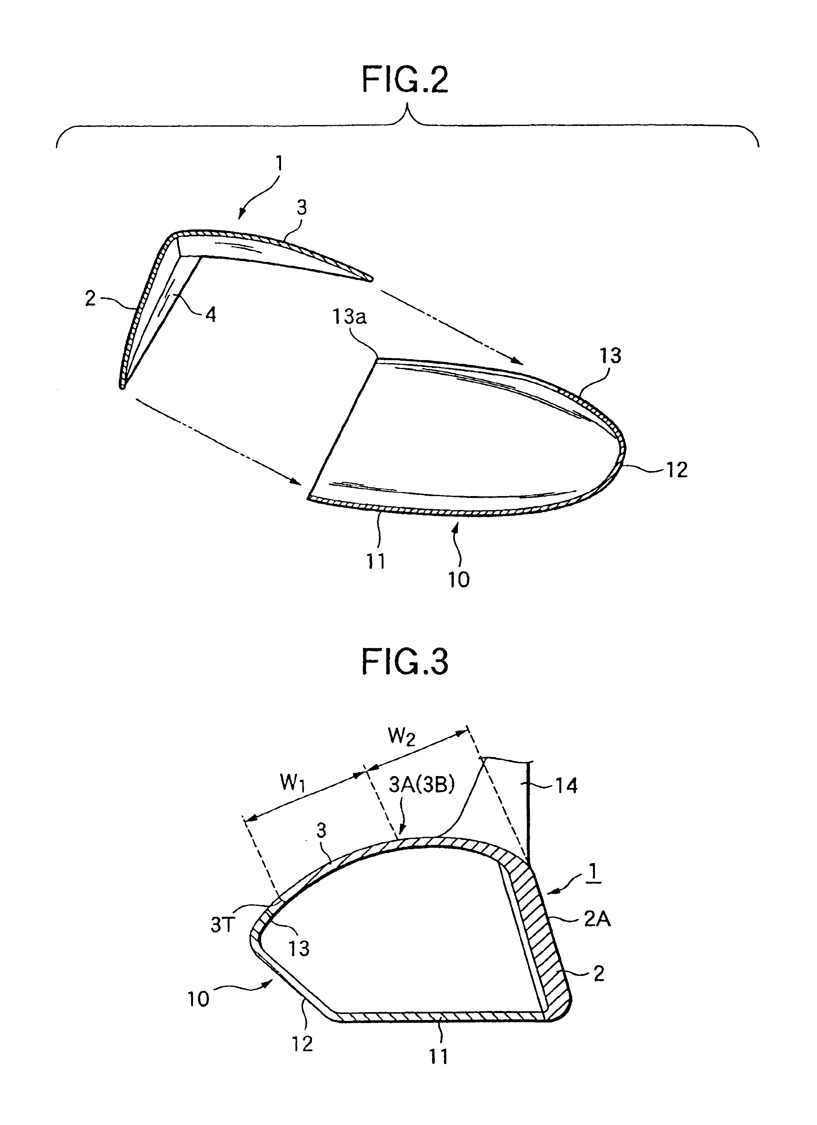
On the other hand, if the thickness near the point 3A was larger than 1.2 mm, sufficient bending could not be obtained.
However, if the center area is made too thick, the face surface side increases in weight so that the center of gravity is located forward.
Thus, for a wood type golf club, particularly for a club with a loft angle lower than 15.degree., a ball becomes difficult to launch upward.
However, if the head volume or the head height were too large, the head would not be suitable as a golf club head.

Method used


Image

  • Golf club head
  • Golf club head
  • Golf club head

Examples


examples 1 and 2

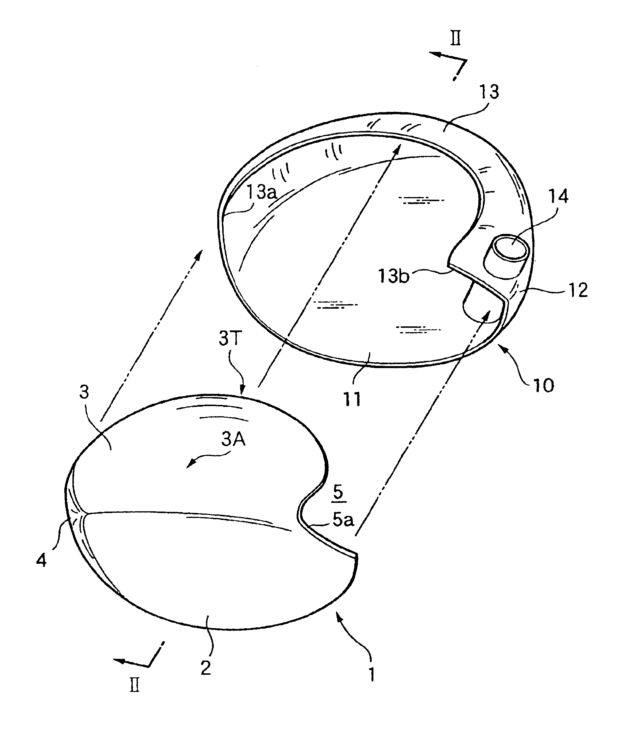
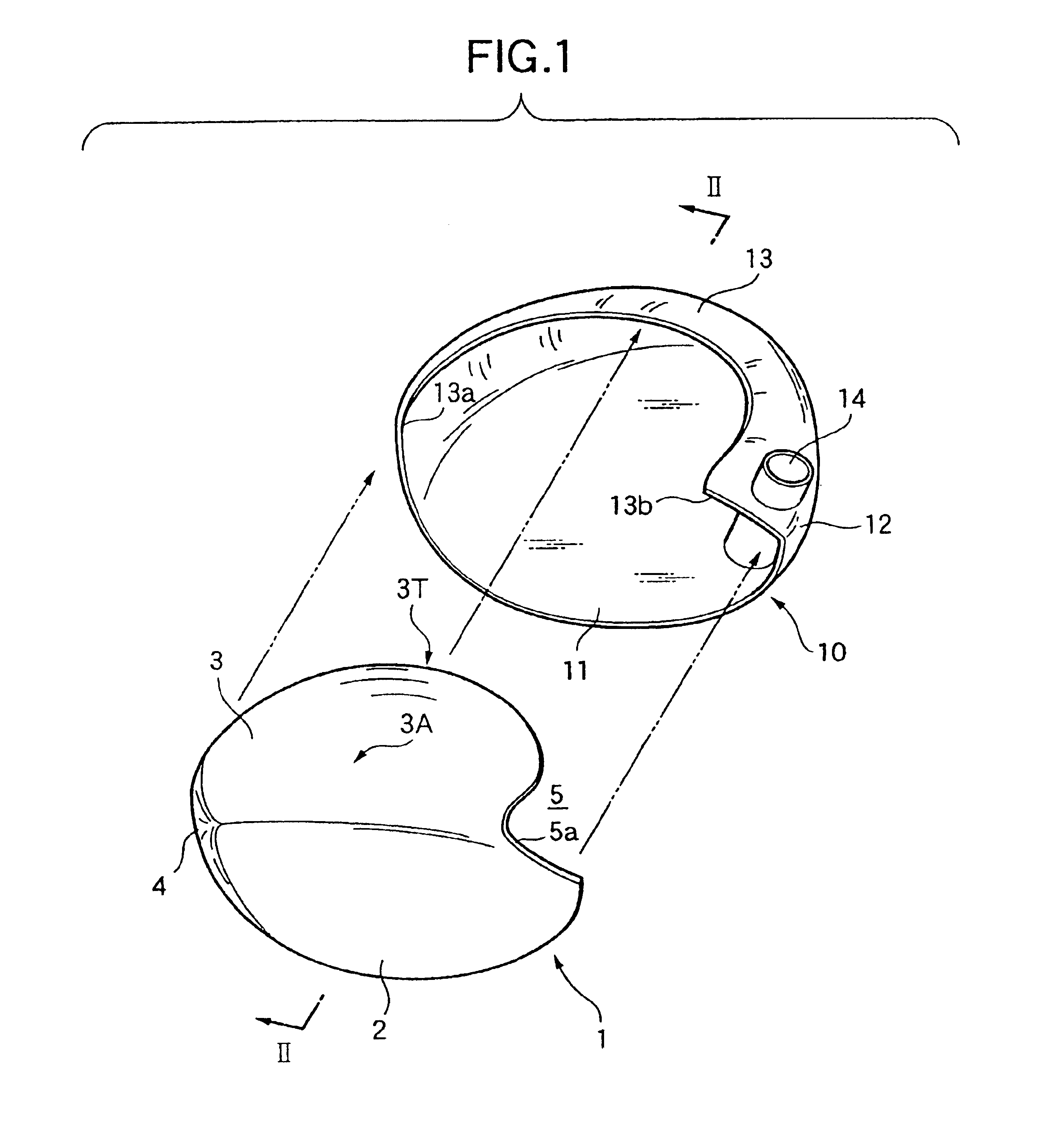
Golf club heads in Examples 1 and 2 had a configuration described in the embodiment 1. In Example 1, a Ti-6Al-4V alloy was used for the front part 1 formed by integrally casting the face portion and the crown portion. On the other hand, in Example 2, a Ti-6Al-7Nb alloy was used. The thickness of the center portion of the face portion was set to 3 mm, and the thinnest portion of the peripheral portion of the face was set to 2.5 mm. The average thickness of the crown portion was set to about 1.2 mm, and the thickness of the vicinity of the crown highest portion was set to about 0.9 mm. The head body portion including the sole portion and the hosel portion was produced by casting with a Ti-6Al-4V alloy in each of Examples 1 and 2. The thickness of the sole portion and the side portion was 1.2 mm.

A margin having a welding thickness of 1.5 mm was provided in the welded portion other than the face portion between the front part 1 and the back part 10. The front part 1 and the back part 10...

example 3

A golf club head of the example 3 has a structure described in the embodiment 2. A round bar of a Ti-4.5Al-3V-2Mo-2Fe alloy (SP700) produced by a forging machine was used to manufacture a golf club head according to the present invention shown in FIG. 11. First, this round bar was heated to about 800.degree. C., and a face portion and a crown portion were molded integrally by hot forging. This molding was performed through three times of hot forging stages of rough forging, main forging and finish forging.

In the obtained front part, the thickness of a center of the face portion was 2.7 mm, the thick ness of a periphery of the face portion was 2.3 mm, and two ribs 3 mm wide and 0.3 mm high were provided in a back surface portion. These ribs were provided to extend in the height direction of the face portion and substantially over the whole area of the height thereof. The ribs were formed at an interval of 30 mm so that the center portion between the ribs was located in the face cente...


PUM


Abstract

This golf club head is constituted by a front part 1 including a face portion 2 and a crown main portion 3, and a back part 10 forming the remaining portion of the golf club head. A metal material forming the front part 1 has lower Young's modulus than that of a metal material forming the back part 10. The front part 1 and the back part 10 are welded. The thickness of the center of the face portion 2 is larger than the thickness of the periphery thereof. The thickness of the vicinity of a highest point 3A of the crown is small.

Description

1. Field of the InventionThe present invention relates to a golf club head having a hollow shell made of metal, and particularly relates to a golf club head in which a shell made of metal is thin enough to be deformed easily at a time of hitting a ball, so that a repulsive property is superior, and a large carry can be obtained.2. Description of the Related ArtHollow golf club heads made of metal are used widely as wood type golf club heads such as drivers or fairway woods. Generally, as shown in FIG. 14, a hollow wood type golf club head 321 has a face portion 322 for hitting a ball, a crown portion 323 forming a top surface portion of the golf club head, a sole portion 324 forming a bottom surface portion of the golf club head, a side portion 325 forming the toe-side, rear-side and heel-side side surface portions of the golf club head, and a hosel portion 326. A shaft 327 is inserted into the hosel portion 326 of the golf club head 321, and fixed thereto by a bonding agent or the ...

Claims


Application Information

Patent Timeline
Patent Type & Authority Patents(United States)
IPC IPC(8): A63B53/04
CPCA63B53/04A63B53/0466A63B2053/0408A63B2053/0412A63B2053/045A63B2053/0458A63B2053/0454A63B2053/0416A63B53/0408A63B53/0412A63B53/0416A63B53/045A63B53/0454A63B53/0458A63B60/00
Inventor SEKI, TERUAKIHIRUTA, MASAOMIMATSUNAGA, HIDEO
Owner BRIDGESTONE SPORTS
Learn More