Recording head

a head and recording technology, applied in the field of recording heads, can solve the problems of reducing coupling loss, increasing the number of optical components and beam loss, and complicated mounting of the optical system of the optical components

Inactive Publication Date: 2008-03-06
HITACHI LTD
View PDF3 Cites 100 Cited by
  • Summary
  • Abstract
  • Description
  • Claims
  • Application Information

AI Technical Summary

Benefits of technology

[0050]According to the present invention, the beam from a laser source can be guided to an optical transducer, etc. with a lower loss than that of the prior art.

Problems solved by technology

The means in which the LD element is placed at a position away from the head has an advantage that the limitation on the size and the mounting shape of the LD element can be relaxed, but there is a disadvantage that the number of optical components and the beam loss become greater.
Moreover, a disadvantage also exists in which mounting of the optical system of the optical components becomes complicated.
Moreover, simple mounting which uses a small number of optical components decreases the coupling loss.
However, in the case of an optical head and a magnetic head which use optical near-field, the order of the size of the LD element is the same as the head and it is a size which cannot be ignored.
Therefore, mounting an LD element carelessly on the head which flies over the disk rotating at high speed may influence the movement of the head.

Method used


Image

  • Recording head
  • Recording head
  • Recording head

Examples


first embodiment

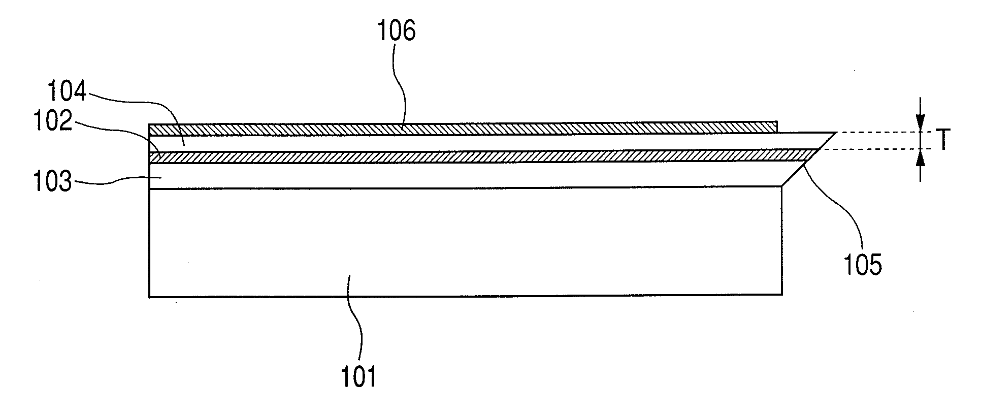
[0066]FIG. 6 is a cross-sectional drawing along the direction of the cavity of an LD element in a recording head on which a semiconductor LD element is mounted, where a reflector of the embodiment in this invention is monolithically integrated. FIG. 7 is a perspective drawing illustrating the same structure. The LD element monolithically integrates the reflector 105 and emits beam from the face of a side opposite the substrate 101. The aforementioned LD element includes the active layer 102 in a direction parallel to the upper face of the slider 111, and the surface of the side closer to the active layer 102, that is, the face of the side opposite the substrate 101 approaches the upper face of the slider 111 and is mounted. The optical emission position of the LD element is mounted to adjust to the optical injection position of the optical waveguide 113 formed in the slider. Solder 112 is placed over the upper face of the slider and mounted to be welded to the electrode 106 of the L...

second embodiment

[0068]FIG. 9 is a cross-sectional drawing along the direction of the cavity of an LD element in a recording head on which a semiconductor LD element is mounted where a reflector of the embodiment in this invention is monolithically integrated. FIG. 10 is a perspective drawing illustrating the same structure. It is an example in which the face for mounting an LD element is made lower by the same amount as the height corresponding to the thickness of the adhesive used for mounting.

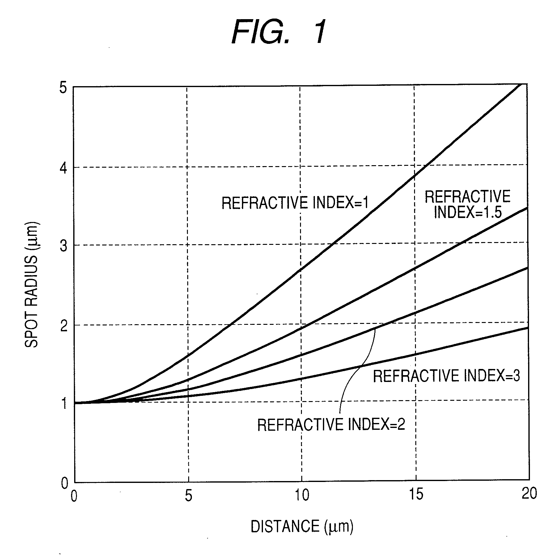
[0069]When the LD element is mounted over the slider, a solder is used for a conductive adhesive. Since solder usually has a thickness of several microns, a gap is created by the same amount corresponding to the thickness of the solder between the optical emission position of the LD element and the injection position of the optical waveguide over the slider. In order to improve the optical coupling efficiency by compensating for the amount corresponding to the thickness, the part for mounting the LD element ...

third embodiment

[0070]FIG. 11 is a cross-sectional drawing along the direction of the cavity of an LD element in a recording head on which a semiconductor LD element is mounted where a reflector of the embodiment in this invention is monolithically integrated. FIG. 12 is a perspective drawing illustrating the same structure. It is a structure where a submount 121 is sandwiched between the LD element and the slider, and active alignment can be applied by adopting this structure. An adhesive 122 is used for the joint between the submount 121 and the slider 111. A metallic solder and a chemical adhesion system resin can be used for the adhesive 122.

[0071]FIG. 13 is a schematic drawing illustrating a state where the LD element and the submount are mounted over the slider. At first, the LD element where the reflector is integrated is mounted over the submount 121. Lead lines 116 and 117 for the LD drive power supply are provided over the submount and the p-electrode and n-electrode are connected to each...


PUM

PropertyMeasurementUnit
wavelength rangeaaaaaaaaaa
sizeaaaaaaaaaa

Abstract

It is an objective that the optical loss and the number of optical components are reduced in an optical recording head using a near-field where a laser beam is guided from a light source to the tip of the head and a thermally assisted magnetic recording head. A structure where the traveling direction of emitted beam is rotated in the direction of the cavity of the laser diode element and a reflector for guiding the beam to the surface of the surface of the laser diode element is monolithically integrated in the laser diode element is mounted over the slider so that the direction of the cavity of the laser diode element is parallel to the surface of the recording medium, and the substrate side of the laser diode element is mounted to be in the direction opposite the face adjacent to the upper face of the slider.

Description

CLAIM OF PRIORITY[0001]The present application claims priority from Japanese application JP 2006-233043 filed on Aug. 30, 2006, the content of which is hereby incorporated by reference into this application.FIELD OF THE INVENTION[0002]The present invention relates to a recording head, and, specifically, relates to an information recording device with high recording density, an optical recording device which includes an optical recording medium and a means for writing on the recording medium by using a laser beam, and an optical / magnetic hybrid recording device which includes a magnetic recording medium, a means for writing on the recording medium by a magnetic field, and a means for heating the recording medium by using a laser beam. Specifically, it relates to a head for an optical disk which includes a structure for guiding a laser beam to the recording medium and performs recording by using a near-field light and a hybrid magnetic recording head which includes a structure and a r...

Claims


Application Information

Patent Timeline
Patent Type & Authority Applications(United States)
IPC IPC(8): G11B11/00
CPCG11B5/314G11B7/124G11B5/105G11B2005/0021G11B7/1387
Inventor SHIMIZU, JUNICHIRO
Owner HITACHI LTD
Why Eureka
Try Eureka