Transmission apparatus, transmission method, reception apparatus, and reception method

Inactive Publication Date: 2009-12-03
NTT DOCOMO INC
View PDF8 Cites 113 Cited by
  • Summary
  • Abstract
  • Description
  • Claims
  • Application Information

AI Technical Summary

Benefits of technology

[0010]According to the present invention, the data channel transmission efficiency can be

Problems solved by technology

Since a receiver receives signals with various trans

Method used


Image

  • Transmission apparatus, transmission method, reception apparatus, and reception method
  • Transmission apparatus, transmission method, reception apparatus, and reception method
  • Transmission apparatus, transmission method, reception apparatus, and reception method

Examples


example 1

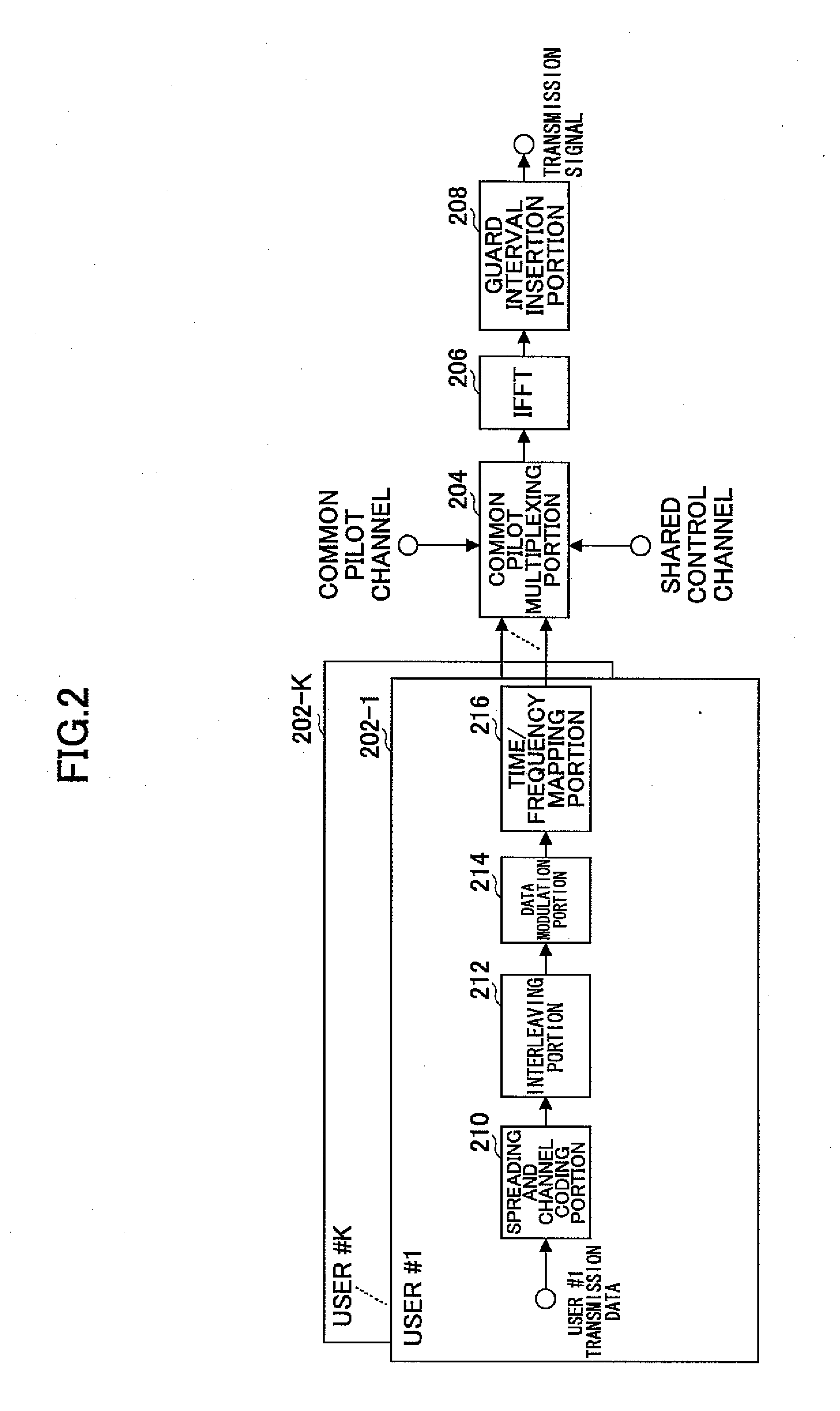
[0087]FIG. 2 shows a part of a transmitter according to a first example of the present invention. Although this transmitter is typically provided in a radio base station of a mobile communications system as described in this example, the transmitter may be provided in other apparatuses. The transmitter has plural data channel processing portions 202-1 to 101-K, the number of which is K, a common pilot multiplexing portion 204, an IFFT portion 206, and a guard interval insertion portion 208. Since the K data channel processing portions 202-1 to 202-K have identical functions and configurations, a first data channel processing portion 202-1 represents the others in the following explanation. The data channel processing portion 202-1 has a spreading and channel coding portion 210, an interleaving portion 212, a data modulation portion 214, and a time and frequency mapping portion 216.

[0088]The data channel processing portion 202-1 processes a data channel for a first user. While one da...

example 2

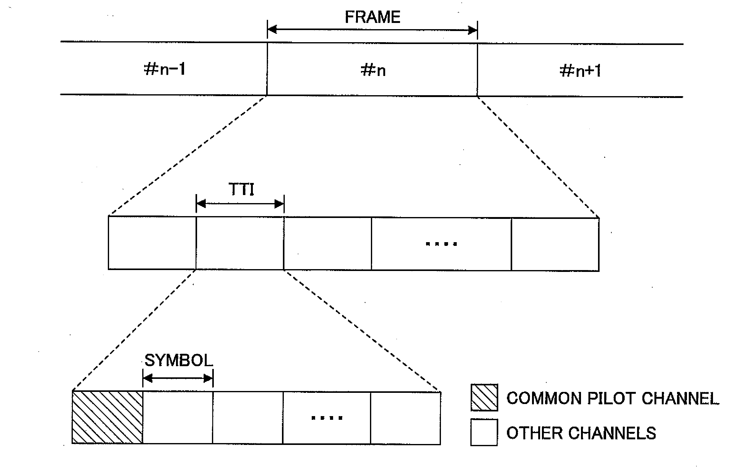
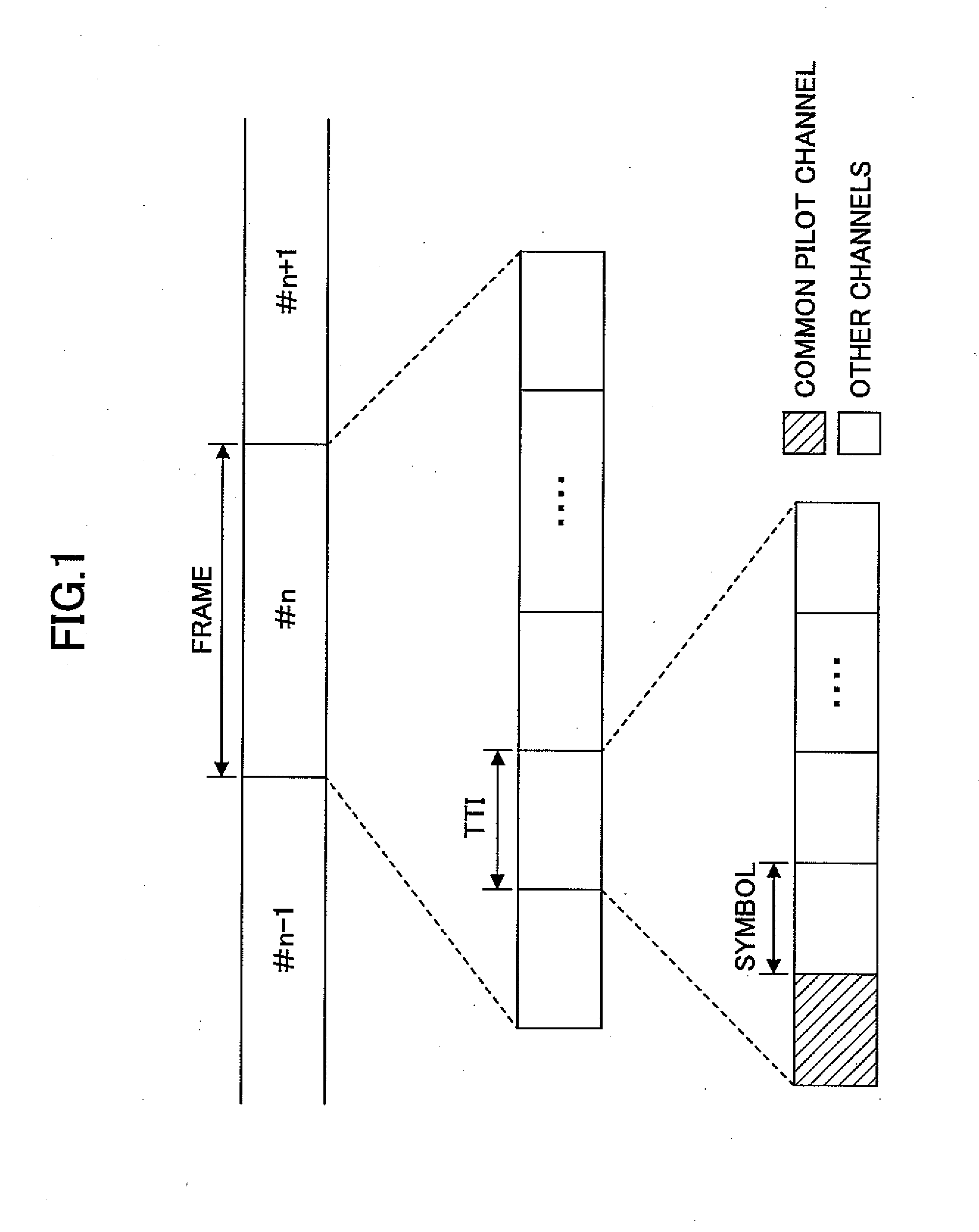
[0114]In a second example of the present invention, the dedicated pilot channels are used in addition to the common pilot channels. These channels are the same in that these channels are used for the channel estimation or the like. However, these channels are different in that the dedicated pilot channels are used only for a particular mobile station while the common pilot channels are used for all the mobile stations. Therefore, while only one kind of signal may be prepared as a signal indicating the common channel, plural kinds of signals have to be prepared as signals indicating the dedicated pilot channels, the number of which is larger than the number of the mobile phones. The dedicated pilot channels are used when the mobile phones move at higher moving velocity, when a directional beam is used in downlink, and when the mobile stations have the predetermined number of reception antennas, or the like, the details of which are explained below.

[0115]FIG. 6 shows various channel c...

example 3

[0117]FIG. 8 shows a part of transmitter according to a third example of the present invention. In FIG. 8, like numerals are given to the elements that have been already explained in reference to FIG. 2. As shown, the data channel processing portion 202-1 additionally has a dedicated pilot channel control portion 72 and a dedicated pilot channel multiplexing portion 74. These elements are provided in the other data channel processing portions 202-2 to 202-K. The dedicated pilot channel control portion 72 determines, in accordance with mobility of a mobile station concerned, whether the dedicated pilot channels are inserted into a signal to be transmitted to the mobile station. The mobility may be measured, for example, through the maximum Doppler frequency. When the measured mobility exceeds a predetermined level, the dedicated pilot channels may be inserted. The dedicated pilot multiplexing portion 74 inserts or does not insert the dedicated pilot channels to the signal to be trans...


PUM


Abstract

A disclosed transmission apparatus includes a multiplexing portion that multiplexes a common pilot channel, a shared control channel, and a shared data channel; a symbol generation portion that performs an inverse Fourier transformation on the multiplexed signal so as to generate a symbol; and a transmission portion that transmits the generated symbol. The multiplexing portion multiplexes the shared control channel including control information necessary for demodulation of the shared data channel including a payload and the common pilot channel to be used by plural users in a frequency direction, and the shared data channel in a time direction with respect to the common pilot channel and the shared control channel. Even when the number of symbols composing a transmission time interval (TTI) is reduced, transmission efficiency of channels excluding the common pilot channel can be maintained by reducing insertion intervals of the common pilot channel accordingly.

Description

TECHNICAL FIELD[0001]The present invention relates generally to a mobile communications field of technology, and specifically to a transmission apparatus, a transmission method, a reception apparatus, and a reception method for use in an Orthogonal Frequency Division Multiplexing (OFDM) method mobile communications system.BACKGROUND ART[0002]A future mobile communications system that mainly carries out image or data communications requires capabilities far beyond the capability of the conventional mobile communications system (for example, an IMT-2000-based system). To this end, higher capacity, higher speed, broader band or the like have to be realized.[0003]In a broadband mobile communications system, frequency selective fading caused by a multi-path transmission environment tends to be problematic, which makes an OFDM (Orthogonal Frequency Division Multiplexing) method be considered promising as a method of the next generation communications system. In the OFDM method, guard inte...

Claims


Application Information

Patent Timeline
IPC IPC(8): H04J11/00H04B1/707H04B7/04H04B7/06H04B7/10H04J3/00H04J13/18H04J99/00H04W16/28H04W72/04H04W76/00H04W76/02
CPCH04J13/00H04J13/004H04L5/0051H04L5/0037H04L5/005H04L5/0023
Inventor KISHIYAMA, YOSHIHISAHIGUCHI, KENICHISAWAHASHI, MAMORU
Owner NTT DOCOMO INC
Why Eureka
Try Eureka