Accordingly, a primary object of the present invention is to provide an electro-optic window having a discrete photovoltaic device integrally combined with the electro-optic window where no external drive
voltage is needed, no bleaching circuit is required, and no external wiring is necessary.
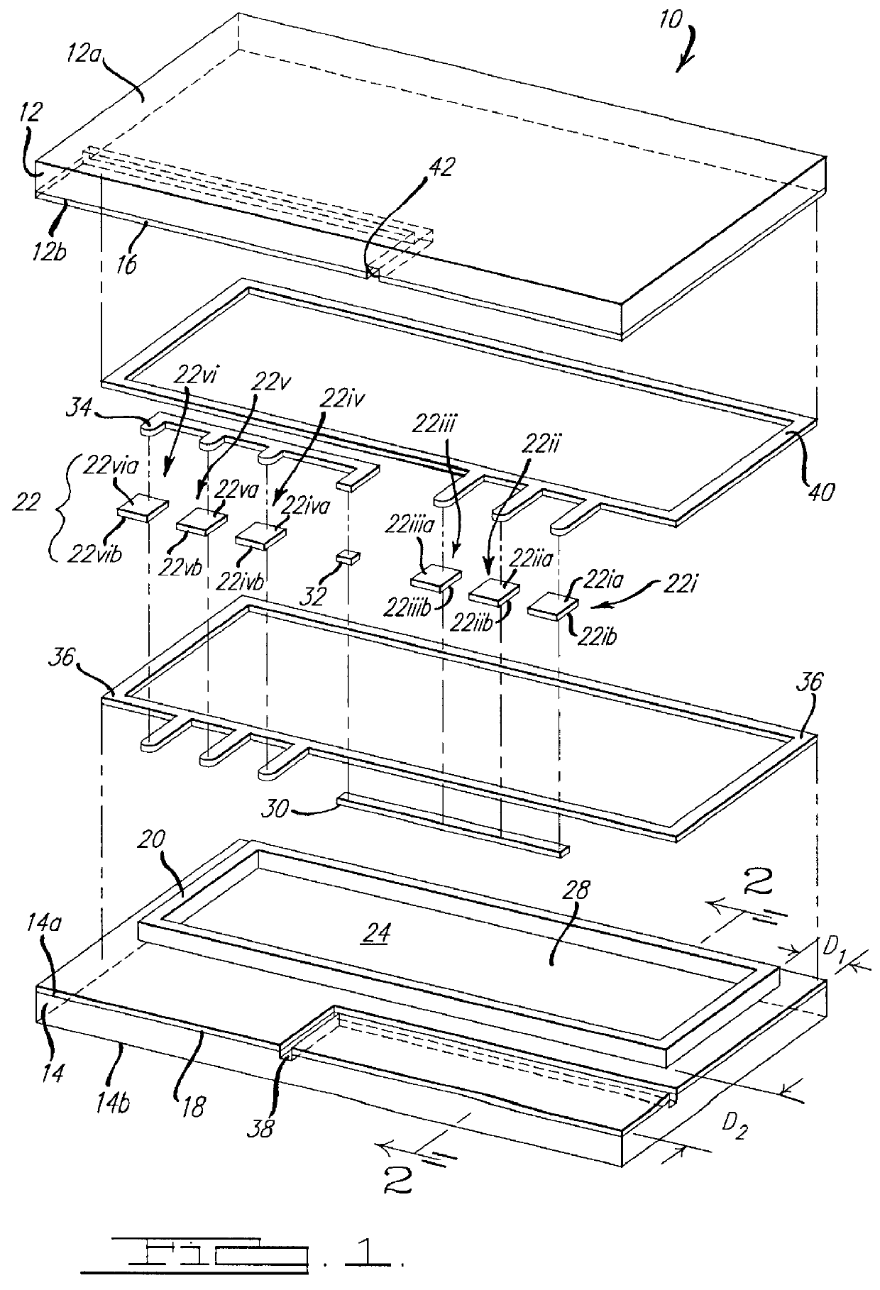
In accordance with the present invention, at least one discrete photovoltaic assembly 22 is enclosed within (or placed between) the two
layers of transparent conductive material (16 and 18) such that the
photon absorbing side 22ia-via of each individual photovoltaic
cell 22i-vi is facing one direction, i.e., out the front face 12a of front element 12. Although shown in FIG. 1 as two sets of photovoltaic cells, those skilled in the art will realize that photovoltaic assembly 22 may be one or more sets of cells and may even be a single cell. An important aspect of the present invention is placing photovoltaic assembly 22 between the two
layers of
conductive materials (16 and 18). This allows the glass elements (12 and 14) to protect the assembly 22 from damage and, since the photovoltaic assembly 22 is in direct contact with the transparent
conductive materials, the need for any external wiring or circuitry is eliminated. The unexpected benefits of this simple design should not be overlooked. Since no clips or other
electrical connection mechanisms are needed to connect the
conductive materials to an
external circuit there are no concerns with the contact stability between the conductive materials and the clips. Furthermore, no separate housing need be constructed for the photovoltaic cells which simplifies the design and decreases the overall costs of the window 10. Finally, as will become more clear by the discussion hereinbelow, the window of the present invention has a cell spacing which uniquely matches commercially available photovoltaic cells. This allows the window design to be simpler in that no wires need to be run to interconnect the photovoltaic cells and the transparent conductive materials (16 and 18).
Photovoltaic devices or solar cells are well known and may comprise a wide variety of p-n junction and
Schottky barrier devices comprising materials such as, but not limited to, polycrystalline-, amorphous- and
single crystal-structures of
silicon,
gallium arsenide,
gallium phosphide,
indium phosphide and
indium antimonide, as well as amorphous
cadmium sulfide,
cadmium selenide,
copper indium selenide,
copper indium
selenide /
cadmium sulfide, and the like. The amorphous structures can be made into thin films which can be easily bonded onto a layer of transparent conductive material and, therefore, allow a plurality of photovoltaic cells to be electrically connected in series (discussed in detail hereinbelow). This makes manufacturing of the overall electrochromic window 10 easier and less costly. The presently preferred photovoltaic cells are
single crystal and
polycrystalline silicon cells.
This is especially important for a photovoltaic-powered device of the present invention. As the sun rises and begins to impinge on the window (and the photovoltaic device), the photovoltaic device generates a current which travels to the two layers of the transparent conductive materials (16 and 18) and a certain electrical potential (P1) is impressed across (and darkens) the electrochromic media 28. When the potential is sufficient for current to flow through an all
solution phase electrochromic media 28, the anodic material is continually being oxidized and the cathodic material is being reduced to replace the anodic and cathodic compounds which diffuse away from the transparent conductive layers and spontaneously react to form non-
colored species in the bulk of media 28. As the sun continues to rise, more light hits the window and more power is generated by the photovoltaic assembly 22 and impressed on the window, the electrochromic media 28 darkens further. As the sun begins to set, less light hits the window and less power is generated by the photovoltaic assembly 22 and impressed on the window. The transmittance of the electrochromic media 28 spontaneously increases to a new level because the number of species being electrochemically
colored is less than before. No other
system allows for this simple and accurate auto-adjustment without complicated circuitry.
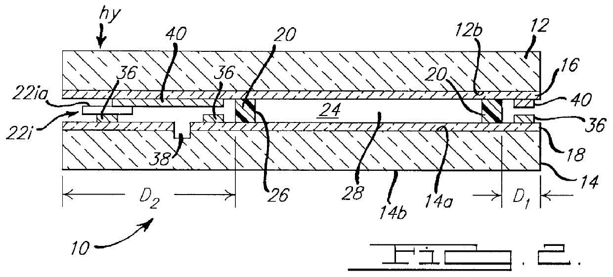
In accordance with another embodiment of the present invention, a spacerless electrochromic window 10 is provided, as is the method for producing such a device. A key aspect of this embodiment is ensuring that the glass elements 12 and 14 are held in a spaced-apart and parallel relationship while the seal material 20 cures. The substrates can be held by a variety of methods, including edge clamps, edge clips and vacuum chucking, with a vacuum chucking
system being preferred. Typically a near vertical cure is preferred to reduce the amount of sag the substrates experienced as a result of gravitational pull, however, with a vacuum chucking
system, since both glass elements are held to a planar vacuum substrate, the glass elements may be bonded in a
horizontal orientation. Referring to FIG. 4, two vacuum-applying members 50 and 52 are provided to contact glass elements 12 and 14 on the sides which are most remote form each other (i.e., the sides that do not confront one another) and apply a vacuum to each glass element. The sealably bonding material 20 is disposed along the periphery of one of the transparent conductive coatings, e.g., material 18, and the second glass element (i.e., transparent
coating 16) is brought into a spaced-apart and parallel relationship with the first glass element such that the circumferential edges of each glass element are substantially aligned. Finally, sufficient heat of UV light is applied to uniformly and completely cure seal material 20. The vacuum-applying members can be held in the spaced apart relationship by a simple spacer 54 such that, as the seal member 20 cures and contracts, the glass elements 12 and 14 may pull away from the vacuum-applying member and reduce the stress in the seal member 20. In a more complicated system, the two vacuum-applying members 50 and 52 can be held in a spaced-apart and parallel relationships by a hydraulics system (not shown) well known in the art. Optionally, the vacuum-applying members can have embedded heaters, or the entire assembly can be heated with infra-red
radiation, a
convection heating oven or other methods well known in the art. It is important, however, that the seal member 20 be heated or, when a
UV curing epoxy is utilized have
radiation applied, in a uniform manner to prevent uneven curing which can produce inconsistencies in the spacing of the substrates.

