
Printer

a printing machine and platen roller technology, applied in printing, typewriters, other printing apparatuses, etc., can solve the problems of time and work consumption, burdensome operation, etc., and achieve the effect of simple structure, easy attachment and detachment of the platen roller portion, and simple structur

Active Publication Date: 2017-08-15
SATO HLDG CORP
View PDF19 Cites 0 Cited by
  • Summary
  • Abstract
  • Description
  • Claims
  • Application Information

AI Technical Summary

Benefits of technology

The present invention aims to make it easier to attach and detach the platen roller portion in a printer. This is achieved by operating the operating portion, which simplifies the attachment and detachment process. The attachment and detachment of the platen roller portion can be made even easier with a simple structure. The platen roller portion can also be made smaller in size, which helps in downsizing the printer. Additionally, the operating lever portion can be adjusted to function as a feed guide of the print medium without interfering with the printing process.

Problems solved by technology

In the techniques that the inventor has examined, when a platen roller portion is attached and detached, installation and removal using screws is required, which is a burdensome operation that consumes time and work.

Method used


Image

  • Printer
  • Printer
  • Printer

Examples


Embodiment Construction

[0043]The following describes an embodiment as an example of the present invention in detail based on drawings. It should be noted that in the drawings to describe the embodiment, an identical reference numeral is basically attached to an identical component, and its repeated description is omitted.

[0044]A feed direction for printing a continuous paper (print medium), specifically a direction feeding the continuous paper from a paper sheet supply unit to a thermal head portion, is referred to as a printing direction, and if there is no specific description, an upstream in the feed direction is referred to as an upstream side in the printing direction, and a downstream in the feed direction is referred to as a downstream side in the printing direction.

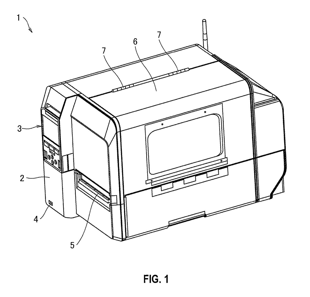
[0045]FIG. 1 is an overall perspective view of an appearance of a printer according to the embodiment.

[0046]A printer 1 according to the embodiment has, for example, a label printing function, which prints information such as a characte...


PUM


Abstract

In a printer that performs printing on a label of a continuous paper while feeding the continuous paper unwound from a paper sheet supply unit, a platen roller portion is configured to be attachable and detachable only by operating an operating lever portion of an attaching and detaching operation portion. The attaching and detaching operation portion has its shaft fixed in a rotatable state between a bearing ring and a platen main body on one side in an axial direction of the platen roller portion. Pulling the operating lever portion of the attaching and detaching operation portion releases a locked state of the attaching and detaching operation portion itself and a locked state in the axial direction of the platen roller portion.

Description

TECHNICAL FIELD[0001]The present invention relates to a printer, for example, a printer having a label printing function that prints desired information, such as a character, a sign, a diagram, a barcode, or similar information, on a label or a similar print medium.BACKGROUND ART[0002]A label printer is a printer having a function that, for example, while unwinding a rolled continuous paper in a sheet-shape to feed the continuous paper, prints desired information on a label of the continuous paper.[0003]This label printer has a printing portion, on which a thermal head portion and a platen roller portion are disposed facing to each other. The thermal head portion is a printing unit, which performs printing on the label. The platen roller portion is a member that feeds the continuous paper, and has its shaft axially supported in a rotatable state on a support frame inside the printer.[0004]A structure regarding this platen roller portion is disclosed, for example, in JP5-80755U that ...

Claims


Application Information

Patent Timeline
Patent Type & Authority Patents(United States)
IPC IPC(8): B41J15/04B41J11/27
CPCB41J15/04B41J11/27B41J11/04B41J3/4075B41J15/046
Inventor ONODERA, HITOSHI
Owner SATO HLDG CORP
Learn More