Releasable wire connector

a technology of releasable wires and connectors, which is applied in the direction of contact members penetrating/cutting insulation/cable strands, instruments, peptides/protein ingredients, etc., can solve the problems of arcing of connector contacts, circuit elements failing and needing replacement, and relatively time-consuming procedures

Active Publication Date: 2007-10-16
IDEAL IND INC
View PDF6 Cites 33 Cited by
  • Summary
  • Abstract
  • Description
  • Claims
  • Application Information

AI Technical Summary

Benefits of technology

[0007]Another object of the invention is a wire connector of the type described including a contact having at least one flexible finger for engaging a conductor inserted into the enclosure. The finger is split to define a main tine and a sacrificial tine. The sacrificial tine is arranged such that it is first to make and last to break contact with a conductor moved into and out of the enclosure, thereby exposing the sacrificial tine to all potential arcing and preventing any arcing to the main tine.
[0009]Yet another object of the invention is a wire connector which provides electrical isolation such that wires can be removed from the connector with no fear of anything coming into electrical contact with live circuit components during removal of the wires.
[0010]The connector has an enclosure which includes a housing and a cap. The housing has at least one compartment defined therein. The housing has a wire port defined at one end and opening into the compartment. The opposite end of the housing is generally open. The cap is slidably engaged with the housing at its open end. The cap also has a wire port defined therein which opens in alignment with the compartment. Each wire port receives one of the wires of a pair to be connected. A contact is mounted in the compartment. The contact has a pair of flexible fingers, one opposite each wire port. The finger is angled with respect to the axis of the wire port. A stripped end of a wire inserted into a wire port flexes the finger as the wire moves past the finger. Thus, the wire is engaged by the finger opposite each port. The finger is biased against the wire which prevents the wire from disengaging the finger. Any tendency of the wire to back out of the wire port merely increases the gripping force of the finger on the wire.
[0011]The cap has at least one inwardly facing plunger formed on it. The plunger is disposed opposite the contact finger at the cap end of the enclosure. The plunger is movable with the cap to selectively engage the finger to bias the finger away from an inserted wire. This releases the pressure of the finger on the wire, allowing the wire to be disengaged from the enclosure. One of the cap or the housing may have a holding feature built into it which will retain the cap in the actuated position until the user has removed the old wire and inserted a new one. Then the user moves the cap out of the actuated position to a retracted position. This permits one-handed operation of the connector.

Problems solved by technology

There are numerous instances in electrical circuits where a circuit element fails and needs replacing.
Replacing such worn out circuit elements traditionally has required a relatively time consuming procedure wherein wires to the failed device are cut and connections of the remaining, existing wiring to the wires of a new device must be made individually.
Another difficulty with releasable, reusable wire connectors is very often the removal of a spent device and the replacement with a new one must be done in a live circuit.
Thus, when old wires are removed and new wires are inserted into a connector, the contacts of the connector are subject to arcing as they break and make contact with the wires of an energized circuit.
The arcing leads to serious degradation of the contacts which can cause them to fail after only a small number of insertions and removals of wires.

Method used


Image

  • Releasable wire connector
  • Releasable wire connector
  • Releasable wire connector

Examples


Embodiment Construction

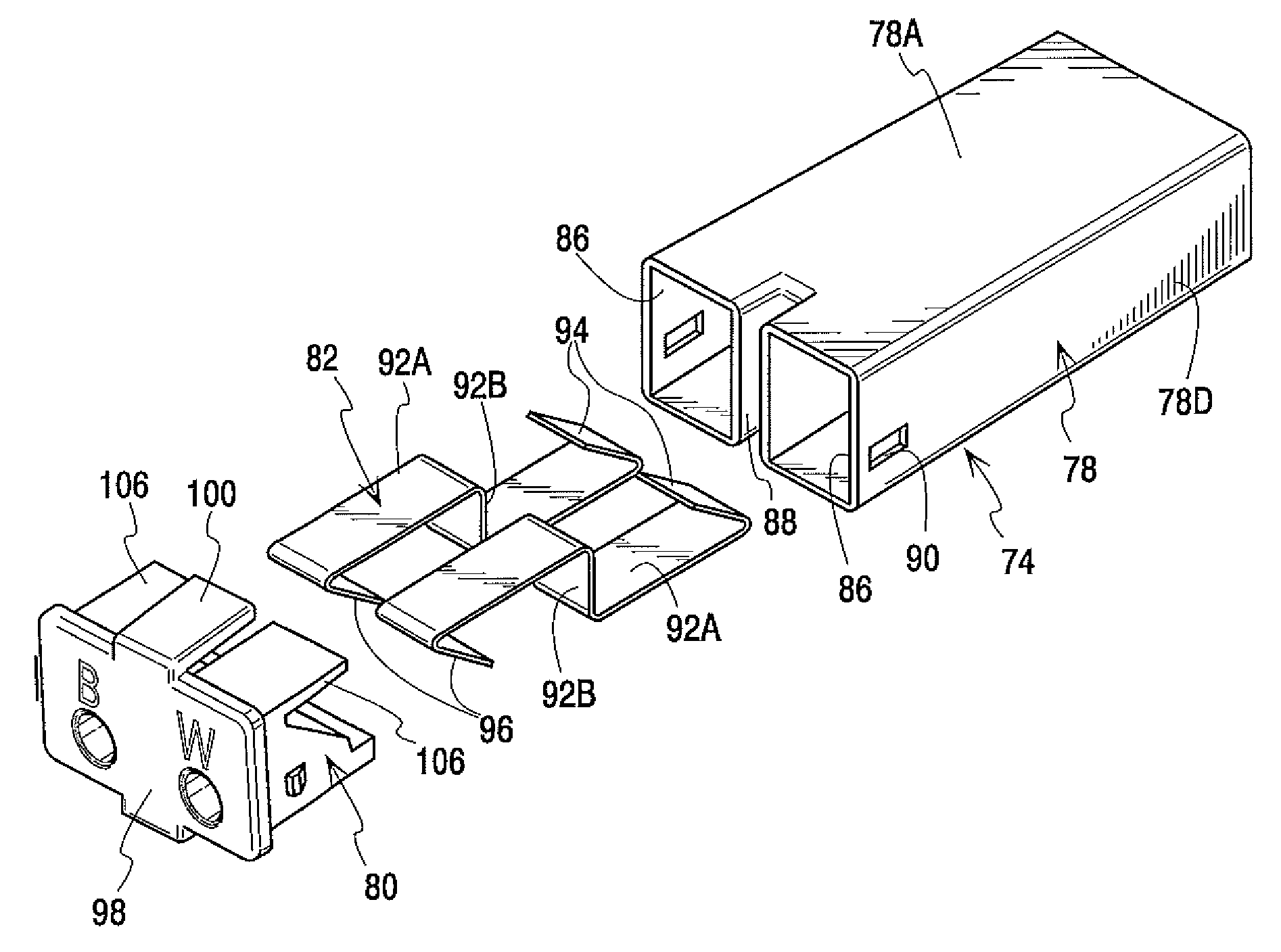
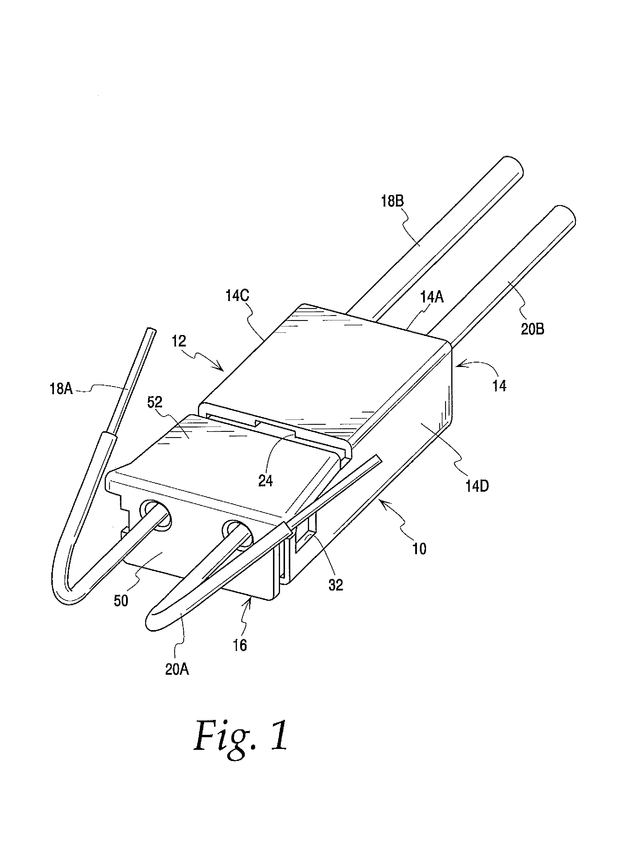
[0033]FIG. 1 illustrates the wire connector of the present invention generally at 10. The wire connector joins pairs of wires in an in-line configuration with push-in connections. That is, the ends of wires to be connected have their insulation stripped to expose bare conductors. The bare conductors are pushed into the connector 10. A contact in the connector engages the conductors and provides a conductive path between them.

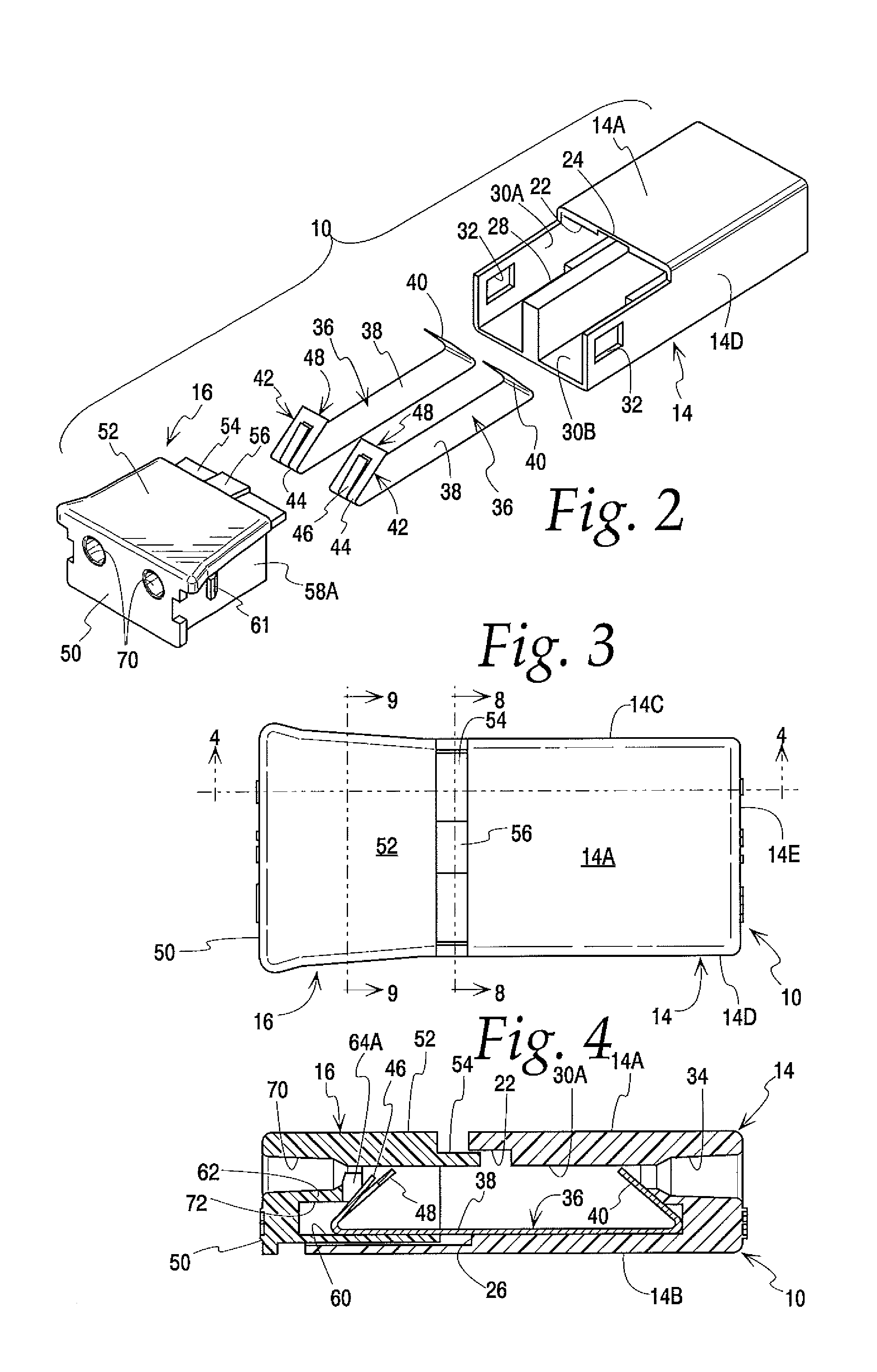
[0034]The connector has a generally hollow enclosure 12. The enclosure includes a housing 14 and a cap 16. The cap is slidably mounted on the housing between actuated and retracted positions. The cap is shown in FIG. 1 in the retracted position. The interior of the cap includes a release block which will be described in detail below. Pairs of wires 18A, 18B and 20A, 20B are shown in FIG. 1 installed in the connector 10.

[0035]Details of the housing are shown in FIGS. 1 and 2. The housing includes top and bottom walls 14A and 14B. These are joined by side walls 14...


PUM

PropertyMeasurementUnit
angleaaaaaaaaaa
angleaaaaaaaaaa
flexibleaaaaaaaaaa

Abstract

A releasable wire connector has a housing and a cap slidably engaging one another and enclosing an electrical contact. The contact has inner and outer flexible fingers disposed opposite wire ports in the housing and cap. The fingers engage conductors inserted into the connector to retain the connectors therein and electrically connect them. The cap carries a release block which will engage some of the fingers and urge them out of engagement with the conductors to allow disengagement of a wire from the connector. One of the fingers may be split into sacrificial and main tines which are arranged so that the sacrificial tine will always be the first to make and the last to break contact with a conductor. Any arcing that may occur will then always be on the sacrificial tine so the main tine will not be degraded by arcing.

Description

CROSS-REFERENCE TO RELATED APPLICATION[0001]This application claims the benefit of U.S. Provisional Application Ser. No. 60 / 737,953, filed Nov. 18, 2005.BACKGROUND OF THE INVENTION[0002]This invention relates to wire connectors and is particularly concerned with a push-in wire connector in which at least one of the wire holding mechanisms is releasable.[0003]There are numerous instances in electrical circuits where a circuit element fails and needs replacing. Ballasts for fluorescent light fixtures are but one example of a circuit element whose life is shorter than other parts of the circuit. Replacing such worn out circuit elements traditionally has required a relatively time consuming procedure wherein wires to the failed device are cut and connections of the remaining, existing wiring to the wires of a new device must be made individually. The time and cost of such procedures could be reduced if the spent device were connected to the circuit by one or more wire connectors that ar...

Claims


Application Information

Patent Timeline
Patent Type & Authority Patents(United States)
IPC IPC(8): H01R4/24
CPCA61K38/46H01R4/4836G01N2500/02H01R2103/00H01R4/48365
Inventor SWEDBERG, BENJAMIN D.BETHURUM, GARY C.
Owner IDEAL IND INC
Why Eureka
Try Eureka