Electrical Disconnect With Push-In Connectors

a technology of push-in connectors and electrical disconnects, which is applied in the direction of multiple conductor connectors, coupling contact members, coupling device connections, etc., can solve the problems of high labor costs of crimping and assembling connectors, inability to move the power to the fixture, and inability to carry the fixture down. , to achieve the effect of preventing shorting, preventing stranded wires from falling off, and enhancing safety

Active Publication Date: 2006-12-21
IDEAL IND INC
View PDF72 Cites 34 Cited by
  • Summary
  • Abstract
  • Description
  • Claims
  • Application Information

AI Technical Summary

Benefits of technology

[0009] Another aspect of the present invention concerns the enclosure provided by the housing. Each push-in contact is shielded by its own, individual compartment. This enhances safety by preventing shorting from one contact to another. No contact is exposed to any other contact because a compartment wall intervenes between any two contacts. Thus, the contacts are shielded not only to the exterior of the housing, but also from any internal shorting paths as well. The contacts are shielded both at the front and rear and whether the housings are engaged or disengaged.
[0010] Yet another feature of the invention is the disconnect can be used with a range of wire sizes and types. Solid or stranded wire from 12 AWG to 18 AWG can be used. The housings have built into them a deflection limiter that prevents a large wire size from flexing the spring fingers of the contacts past their elastic limit. The housings also have wire receptacle boxes that constrain the final location of inserted conductors. This limits movement of the wire within the housing. It also prevents splaying of stranded wires that could reduce the holding force of the spring fingers if it were allowed to occur.

Problems solved by technology

Often this is done in offices, factories, commercial or retail spaces or other facilities where shutting down the power to the fixture is not a practical option.
Unfortunately, electricians occasionally do make errors which result in personal injury and / or property damage.
The labor costs of crimping and assembling the connectors is high and the cost of the connectors themselves is high.
Insulated terminals provide the lowest cost option but these fail to meet the code requirements of simultaneous disconnect of all wires.
Furthermore, insulated terminals are not rated for solid wire and they require crimping by the electrician with its attendant labor cost.

Method used


Image

  • Electrical Disconnect With Push-In Connectors
  • Electrical Disconnect With Push-In Connectors
  • Electrical Disconnect With Push-In Connectors

Examples


Embodiment Construction

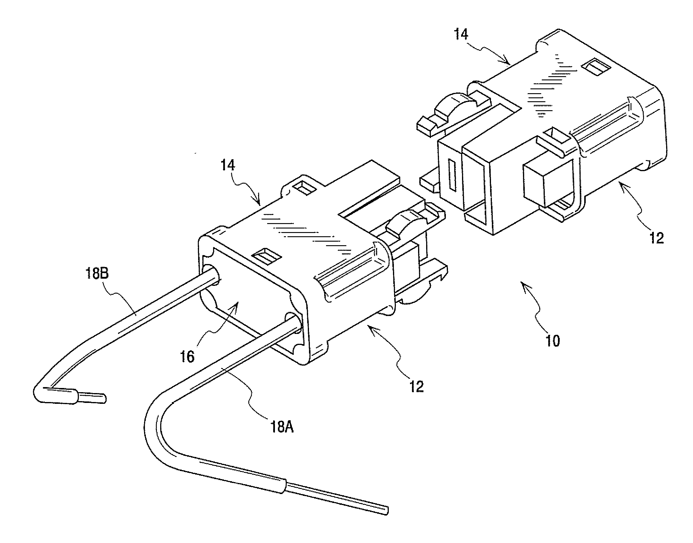
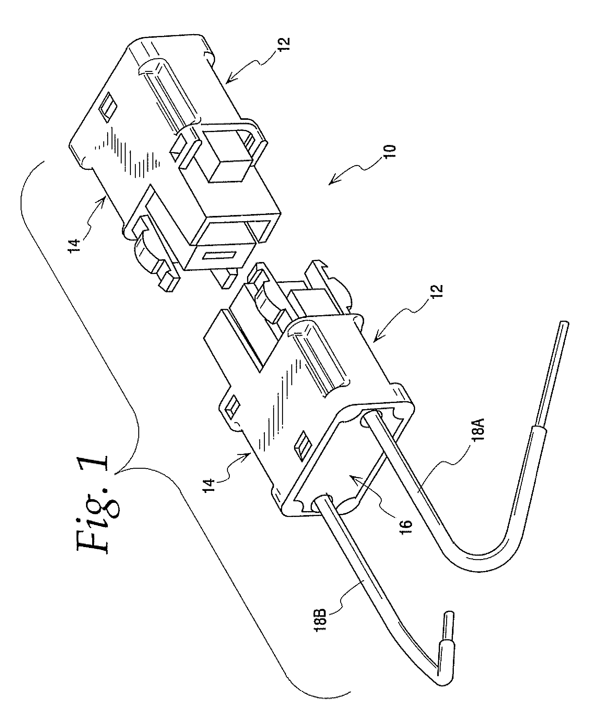
[0076]FIG. 1 illustrates the electrical disconnect of the present invention generally at 10. The complete disconnect includes two identical enclosures 12. Each enclosure includes a housing 14 and a cap 16. The housing can be thought of as a generally five-sided shell with a sixth, outer side that is open to a hollow interior. The cap 16 fits into the shell to close the otherwise open outer end of the housing. Each enclosure also has mounted therein male and female contacts (not shown in FIG. 1). The contacts each have a wire engaging finger at their outer ends and one of a blade or socket at the inner ends. First and second extensions at the inner end of the housing enclose the socket and blade. Wires 18A and 18B electrically connect to the contacts with push-in connections. That is, bare conductors at the ends of the wires are pushed into ports in the cap 16 and engage the finger of a contact. The housing extensions can be releasably plugged into one another to electrically connect...


PUM


Abstract

A wire connector has an enclosure including a housing and a cap and one or more contacts supported in the enclosure. The contacts each have outer ends opposite wire ports in the cap to receive a stripped end of a wire in a push-in engagement. One set of contacts has a male blade and the other set of contacts has a female socket at the inner or forward ends thereof. The housings are arranged so that two housings are releasably engagable with one another. When two housings are engaged the male contacts electrically engages the female contacts of the other housing. The female contacts include a sacrificial tine that is always first to make and last to break engagement with the male contact so that any degradation due to arcing always occurs at the sacrificial tine.

Description

CROSS-REFERENCE TO RELATED APPLICATIONS [0001] This application claims the benefit of U.S. application Ser. No. 60 / 692,631, filed Jun. 21, 2005 and U.S. application Ser. No. 60 / 741,222, filed Dec. 1, 2005.BACKGROUND OF THE INVENTION [0002] This invention concerns a disconnect for electrical circuits. It incorporates a plug and socket combination that provides a convenient and safe way to replace circuit elements in live circuits. A common, but by no means exclusive, application for the disconnect is in non-residential fluorescent light fixtures. Such fixtures require a ballast to operate. Ballasts are typically hard-wired between the power supply and the fluorescent tubes. When a ballast fails it has to be replaced. Traditionally this has been performed by an electrician who cuts the wires to the failed ballast and removes the old ballast. The electrician then installs a new ballast, strips the wire ends, and connects the new ballast's wires to the power supply and tube sockets usin...

Claims


Application Information

Patent Timeline
Patent Type & Authority Applications(United States)
IPC IPC(8): H01R13/40H01R24/58
CPCH01R4/4818H01R11/05H01R11/09H01R13/10H01R13/28H01R13/432H01R24/62H01R13/6273H01R24/20H01R24/28H01R2103/00H01R2107/00H01R13/506H01R4/48185
Inventor BETHURUM, GARY C.SWEDBERG, BENJAMIN D.
Owner IDEAL IND INC
Why Eureka
Try Eureka