Plasma jet apparatus

A plasma and jet technology, applied in the direction of plasma, discharge tube, electrical components, etc., can solve the problems of short plasma jet length, high temperature, unsafe, etc., to widen the application range, improve the application effect, portable good effect

Active Publication Date: 2008-07-23
武汉海思普莱生命科技有限公司
View PDF0 Cites 33 Cited by
  • Summary
  • Abstract
  • Description
  • Claims
  • Application Information

AI Technical Summary

Problems solved by technology

The disadvantage of this device is that the high-voltage electrode 9 is exposed in the external space and is in direct contact with the plasma jet 6, which is not safe for specific applications.
Although there is a dielectric between the high-voltage electrode 9 and the ground electrode 4, due to the close distance, the gap is 0.3 to 1 cm, and arc discharge is prone to occur between the ring holes under high voltage, which is not safe for specific applications.
[0012] As mentioned above, the existing devices all have similar deficiencies, such as: the high-voltage electrodes are improperly placed, and some are exposed directly or partly at the top in the external space, and are in direct contact with the plasma jet; The distance is relatively short, there is a direct connection path in the space, and arc discharge is prone to occur under high voltage; the discharge working gas source is single or can only be a mixed gas mixed with other gases, and the type and quantity of active components in the plasma jet are few; the generated plasma The jet length is short, the temperature is high, and it is difficult to achieve large-scale and large-scale specific applications
These factors have greatly limited the wide application of existing plasma jet technology and devices.

Method used


Image

  • Plasma jet apparatus
  • Plasma jet apparatus
  • Plasma jet apparatus

Examples


Embodiment Construction

[0045] The present invention will be described in detail below with reference to the accompanying drawings.

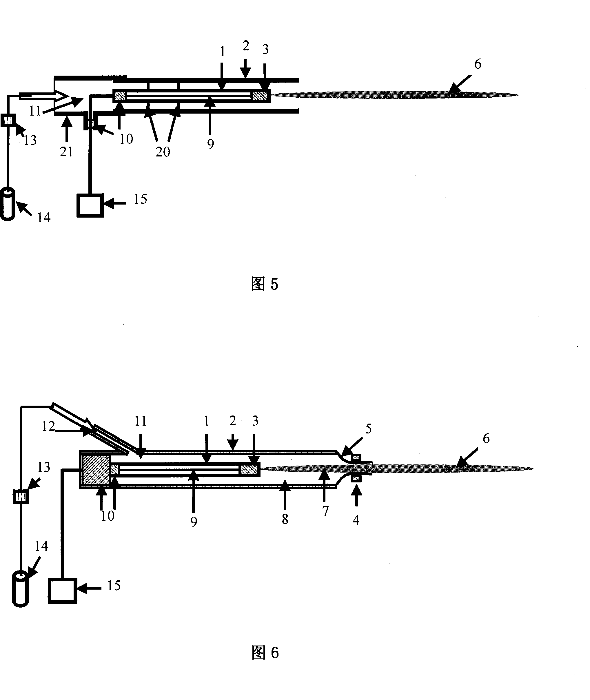
[0046] As shown in Figure 5, the first embodiment of the present invention includes a working gas source 14, a power supply 15, a high-voltage electrode 9, an inner medium pipe 1, and an outer medium container 2, and the high-voltage electrode 9 is placed in the inner medium pipe 1, and Commonly located in the outer medium container 2, the power supply 15 is connected to the high-voltage electrode 9, and the inner medium tube 1 is in the shape of a hollow tube sealed at one end, with a conductive material 3 connected to the high-voltage electrode 9 inside the sealed end, and an insulating plug 10 at the other end , the high-voltage electrode 9 is fixed by the insulating plug 10 and the conductive material 3 , and the inner medium pipe 1 is fixed in the outer medium container 2 by the fixing frame 20 . The high-voltage electrode 9 is connected to the power supply 15 thr...


PUM


Abstract

A plasma body jet flow device belongs to a plasma body generating device and aims at producing plasma body jet flows with long distance, low temperature and rich active compositions, the electrode position is safe, the device is applied in a plurality of discharge. The high voltage electrode of the invention is arranged in an inner dielectric tube and commonly located in an outer dielectric container, power supply is connected with the high voltage electrode, the outer dielectric container is communicated with a working gas source, the inner dielectric tube takes a hollow tubular shape with a sealed single end, the sealed end of the inner dielectric tube is provided with conducting materials which are communicated with one end of the high voltage electrode, the other end of the high voltage electrode in the inner dielectric tube is provided with an insulating plug, and the high voltage electrode is fixed by the insulating block head and the conducting materials. The invention has easy manufacture, good maintenance, safe and convenient use, wide working gas range and changeable temperature, length and thickness of the plasma body jet flows, further develops the range of application of a plasma body technique, and increases the application effects of the plasma body.

Description

technical field [0001] The invention belongs to a plasma generating device, in particular to a gas discharge plasma jet flow device. Background technique [0002] In the prior art, generally speaking, there are two types of discharge plasma sources: one is low pressure plasma; the other is atmospheric pressure plasma, such as corona discharge, dielectric barrier discharge and the like. It can also be divided into equilibrium plasma and non-equilibrium plasma according to the relationship between plasma temperature and electron temperature; according to the plasma temperature, it can be divided into high and low temperature plasma, which have different characteristics and performance, and have different applications. The existing plasma jet devices are mainly divided into the following four types: [0003] (1) AC unbalanced plasma jet device [0004] As shown in Figure 1, Yong Cheol Hong et al. "Microplasma jet at atmospheric pressure" Appl Physics Letter 89, 221504 (2006),...

Claims


Application Information

Patent Timeline
Patent Type & Authority Applications(China)
IPC IPC(8): H05H1/26H01J37/32
CPCH05H1/2406H05H1/2418
Inventor 卢新培潘垣
Owner 武汉海思普莱生命科技有限公司
Why Eureka
Try Eureka