Dual action weightlifting machine

US20070203002A1Active Publication Date: 2007-08-30HOIST FITNESS SYST

Image

  • Dual action weightlifting machine
  • Dual action weightlifting machine
  • Dual action weightlifting machine

Examples


Example

DETAILED DESCRIPTION OF THE DRAWINGS

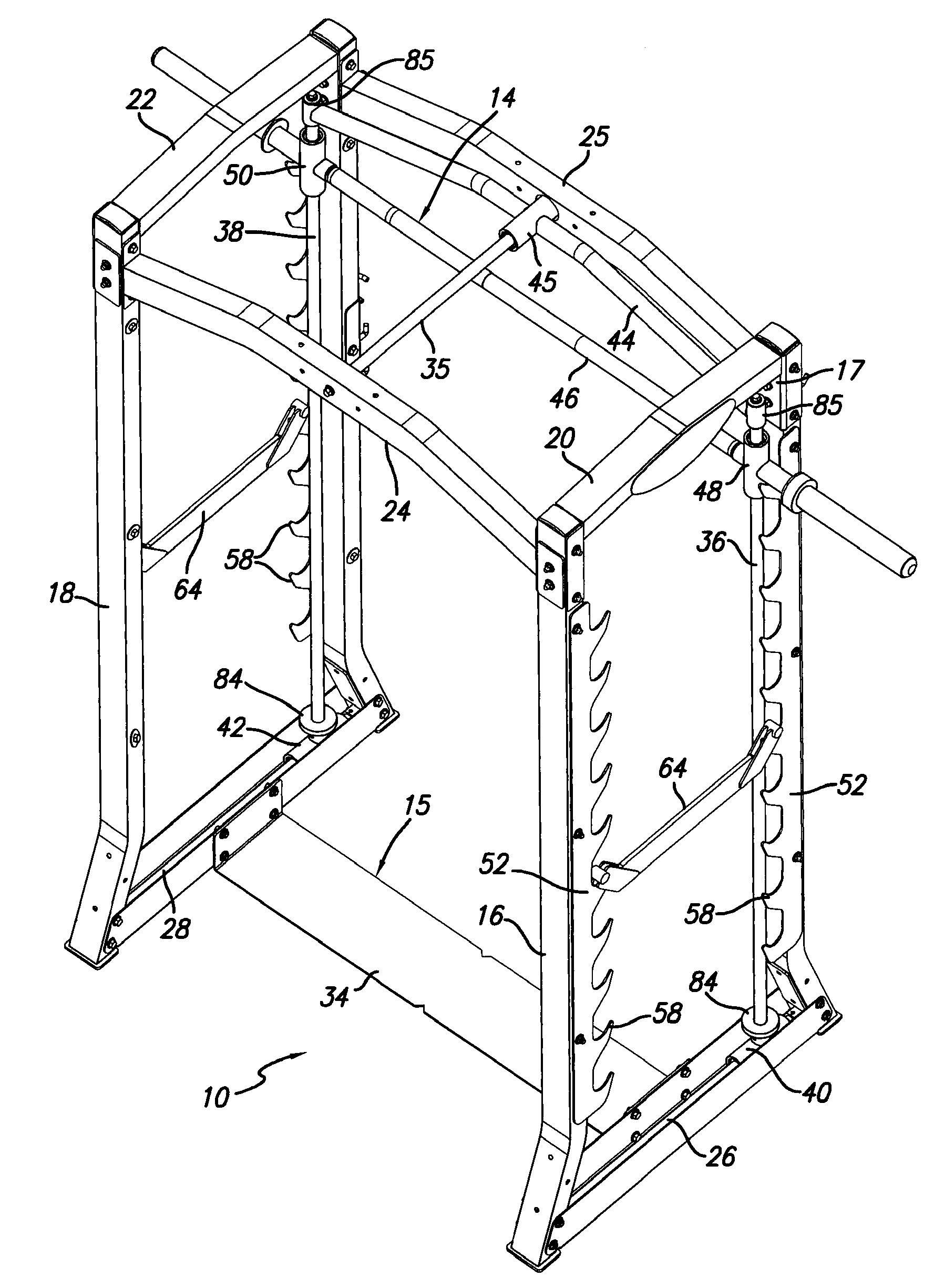
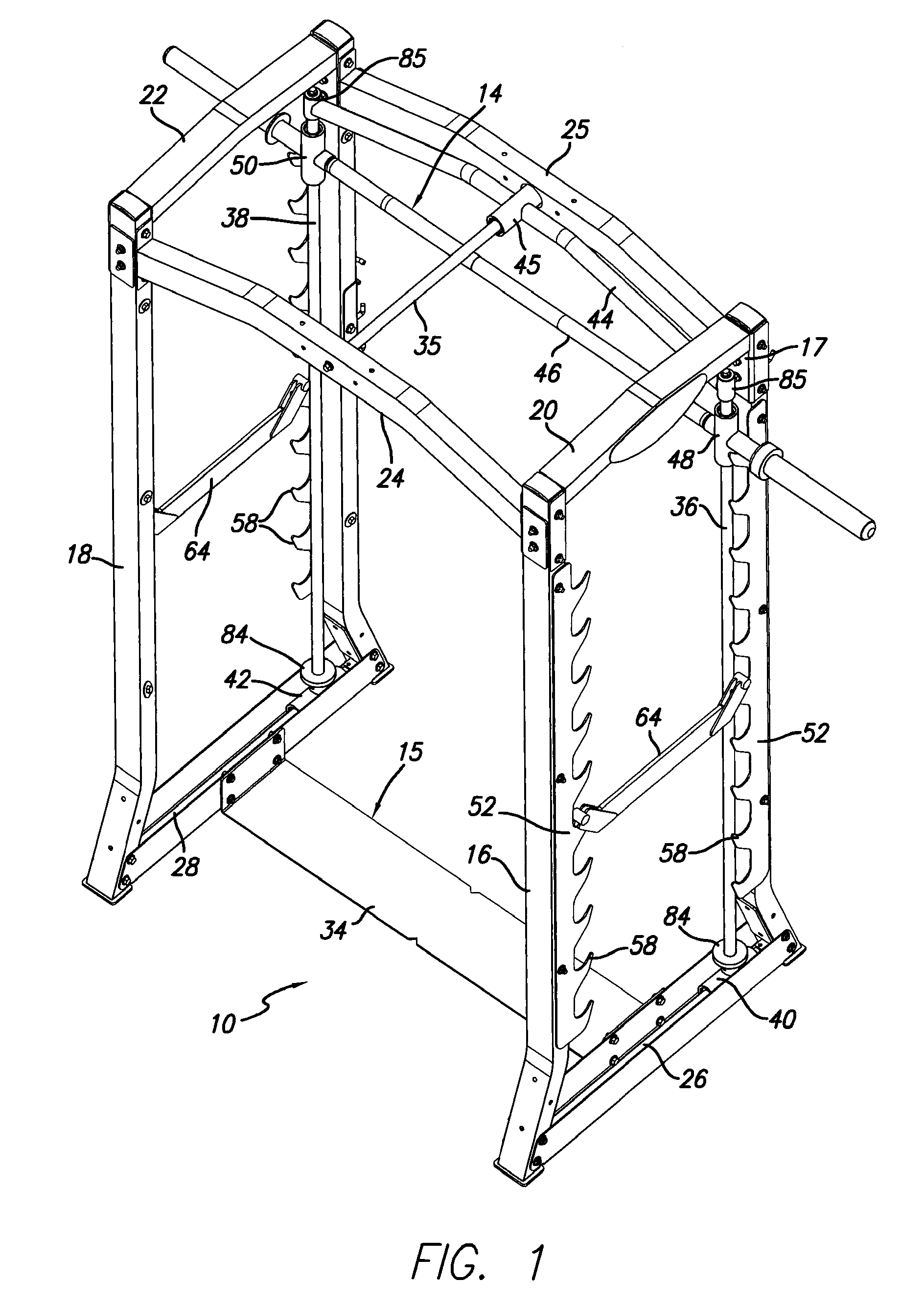
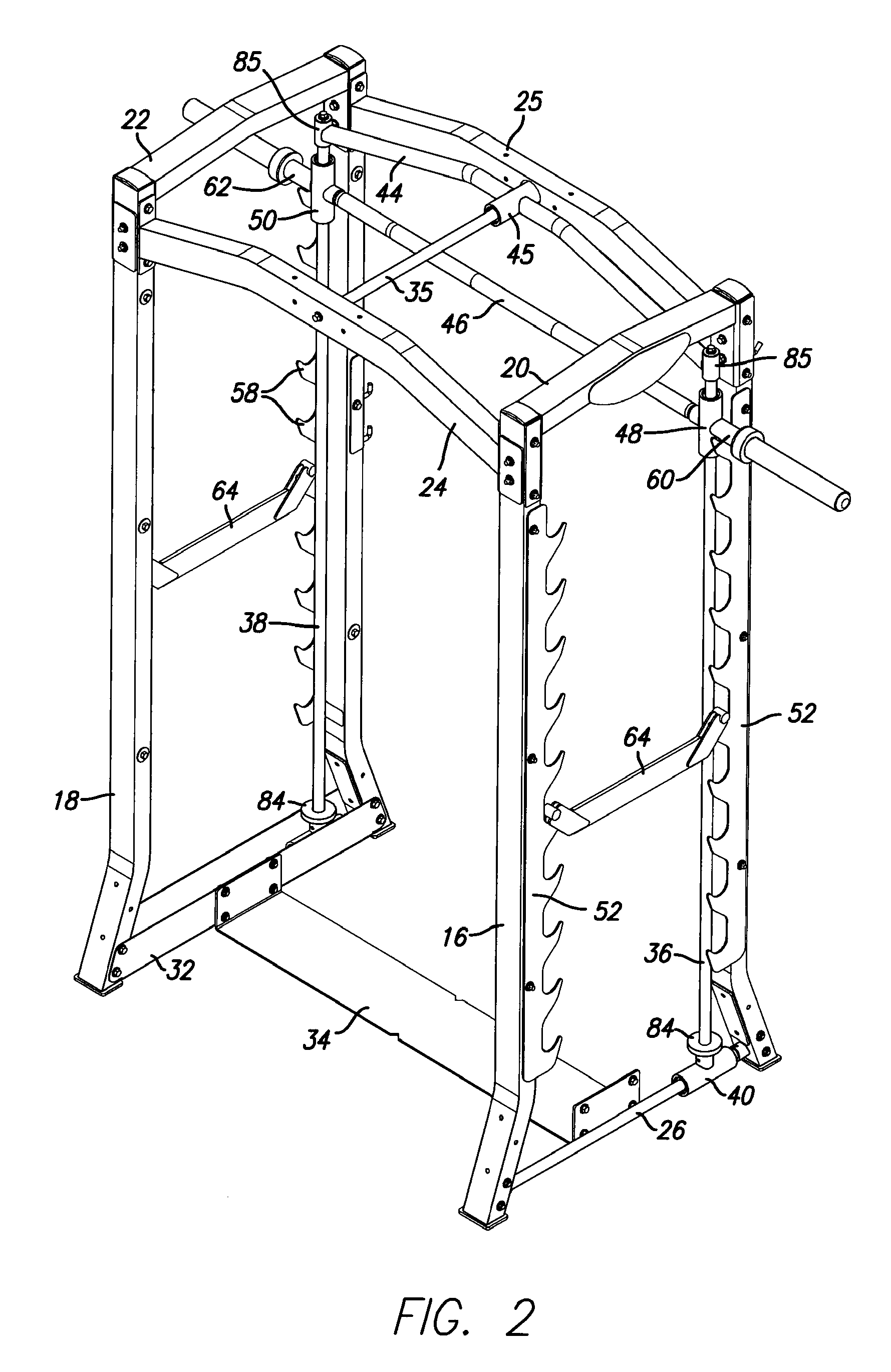
[0058]FIGS. 1 to 10 illustrate a dual action weightlifting exercise machine 10 according to a first embodiment of the present invention. The apparatus basically comprises a stationary main frame 12 and an exercise unit 14 movably mounted on the stationary frame. The movable exercise unit 14 is shown separately in FIG. 9, with most of the stationary frame parts removed for clarity.

[0059]The stationary frame 12 is designed to support the movable exercise unit and comprises a floor engaging base 15, first and second pairs of upright struts 16, 17 and 18, 19, respectively, upper struts 20, 22 extending between the upper ends of each pair of upright struts, and upper cross struts 24, 25, the first upper cross strut 24 extending between the upper ends of the front upright strut 16, 18 of each pair, and the second upper cross strut 25 extending between the upper ends of the second upright strut 17, 19 of each pair. A pair of lower horizontal guide bars 2...


PUM


Abstract

An exercise apparatus for performing simultaneous horizontal and vertical exercise movement has a stationary frame, upper and lower horizontal guides mounted on the stationary frame, and an exercise unit movably mounted on the horizontal guides for horizontal movement relative to the stationary frame. At least one of the horizontal guides is offset from the opposite sides of the frame. The traveling exercise unit has two vertical guides slidably linked with the horizontal guides, at least one traveling cross member linking the two vertical guides, a horizontal slide associated with the traveling cross member and slidably engaged with the offset horizontal guide to slidably link both vertical guides to the horizontal guide, two vertical slides each slidably engaged with a respective vertical guide for vertical linear movement, and a weight bearing exercise bar extending horizontally between the vertical slides. This arrangement allows simultaneous vertical and horizontal movement of the exercise bar.

Description

BACKGROUND OF THE INVENTION[0001]The present invention relates generally to weightlifting exercise machines, and is particularly concerned with exercise machines of the type which simulate free weight barbell exercise movements.[0002]Weightlifting machines with weight bars for simulating barbells, also known as Smith machines, have been a fitness club staple for many years. The basic machine has a barbell attached to slide mechanisms which run on vertical guides on opposite sides of a stationary frame. This allows an exerciser to perform exercises with vertical up and down movement, such as squats, bench press exercises, and the like, but does not permit any horizontal movement. The exerciser does not have to worry about balancing the side-to-side or front-to-back movement of an independent, free weight bar. The premise is that this design provides an additional measure of safety and is easy for the neophyte to use.[0003]The first Smith machines had the vertical guides running perpe...

Claims


Application Information

Patent Timeline
30 Aug 2007
Publication
US20070203002A1
IPC
A63B21/078; A63B26/00
CPC
A63B21/0613; A63B2021/0783; A63B2021/0614; A63B21/078; A63B21/0624; A63B21/0626; A63B21/0783
Inventors
WEBBER, RANDALL T.