Flexible electrical elongated device suitable for service in a high mechanical load environment

a flexible, electrical elongation technology, applied in the direction of flexible conductors, conductors, electrical apparatuses, etc., can solve the problems of large inertia force, high density and low mechanical strength of copper, and inability to meet the load

Inactive Publication Date: 2005-09-13
NEXANS
View PDF8 Cites 43 Cited by
  • Summary
  • Abstract
  • Description
  • Claims
  • Application Information

AI Technical Summary

Benefits of technology

[0009]It is an object of the invention to provide a flexible electrical elongated device suitable for service in a high mechanical load environment by way of example, hanging freely from the sea surface and down to the seabed, in ultra deep water oil field.
[0010]The invention thus aims at providing a reliable load-transferring feature from one or more conductor elements to a load-bearing element in a power cable, thereby ensuring low strains in the conductor element(s).

Problems solved by technology

Although having excellent electrical properties such as high conductivity, copper does not have mechanical properties suitable for withstanding the loads imposed during cable installation and during dynamic service, facing the motions induced by wind, currents and waves, and also the high external pressure at the seabed.
Copper has a high density and a low mechanical strength.
The high density indirectly leads to large inertia forces during installation and dynamic service.
The low mechanical strength implies that copper will not contribute much to the cable's overall strength or axial stiffness.
Furthermore, copper also has a relatively small acceptable maximum strain limit as well as strain range to operate within during dynamic service.
The load transferring mechanism from each conductor element to the load bearing armor layers is internal friction, which is an unreliable servant.
Such high contact forces and relative movement between copper wires may cause fretting to occur.
And copper has relatively low fretting resistance.

Method used


Image

  • Flexible electrical elongated device suitable for service in a high mechanical load environment
  • Flexible electrical elongated device suitable for service in a high mechanical load environment
  • Flexible electrical elongated device suitable for service in a high mechanical load environment

Examples


first embodiment

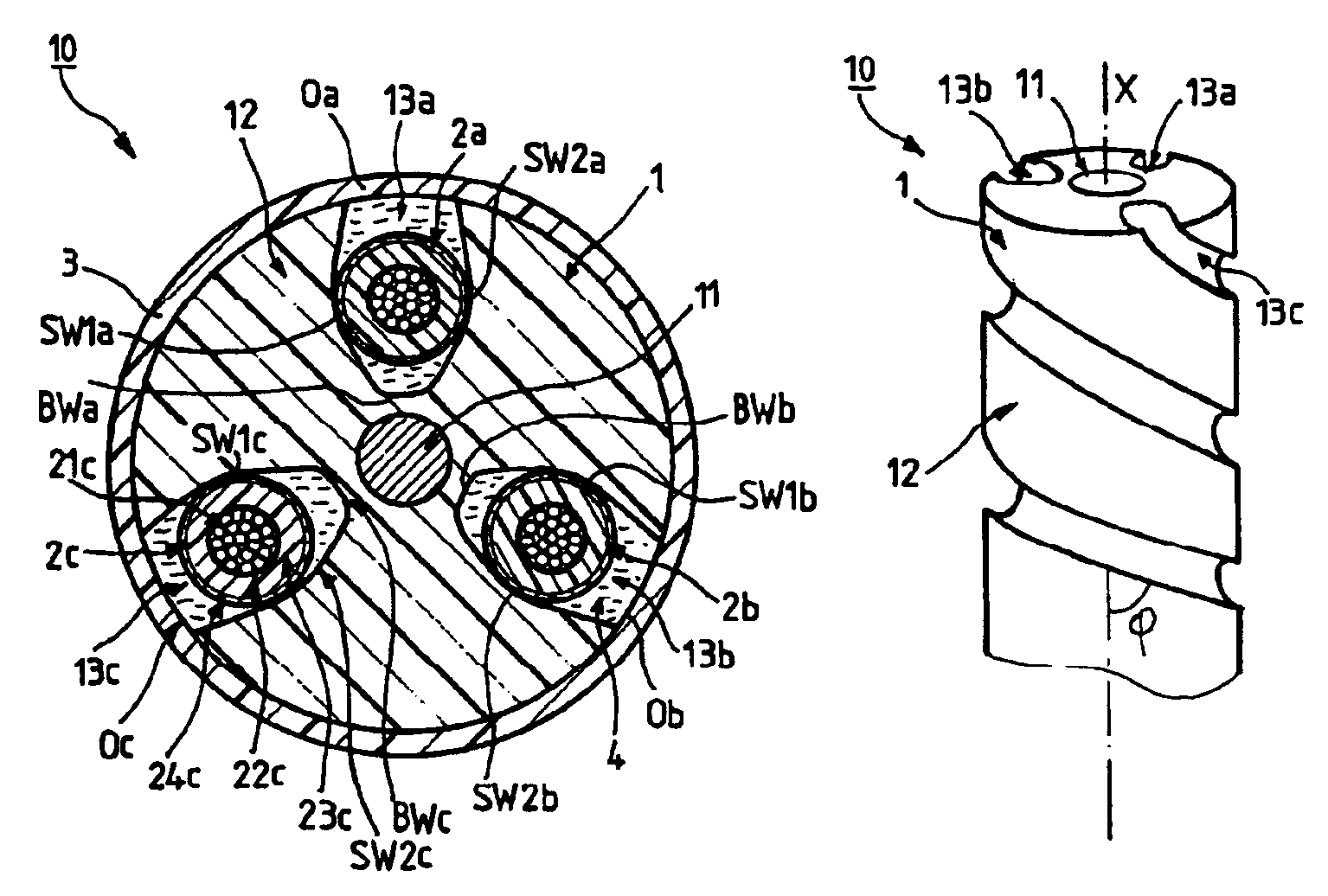
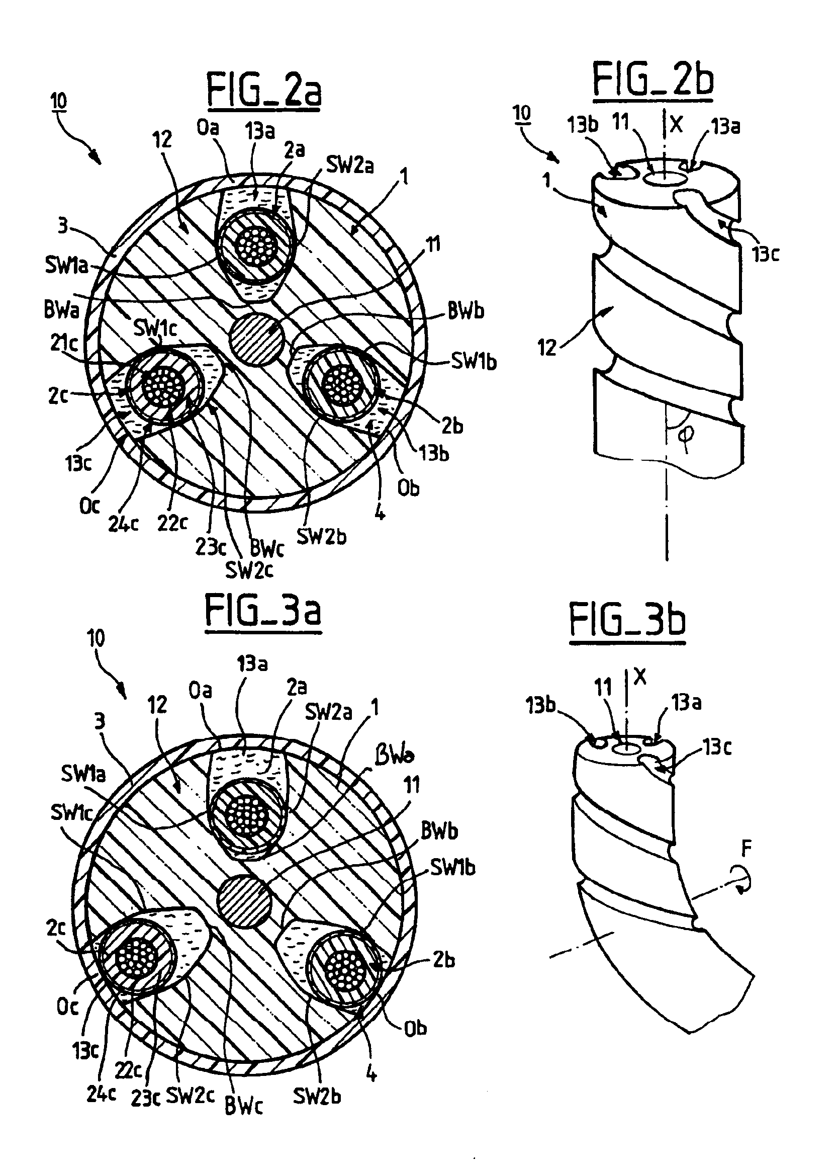
[0055]FIG. 2a is a schematic cross sectional view of a vertical power submarine cable (not to scale) 10 in a straight condition, in the invention.

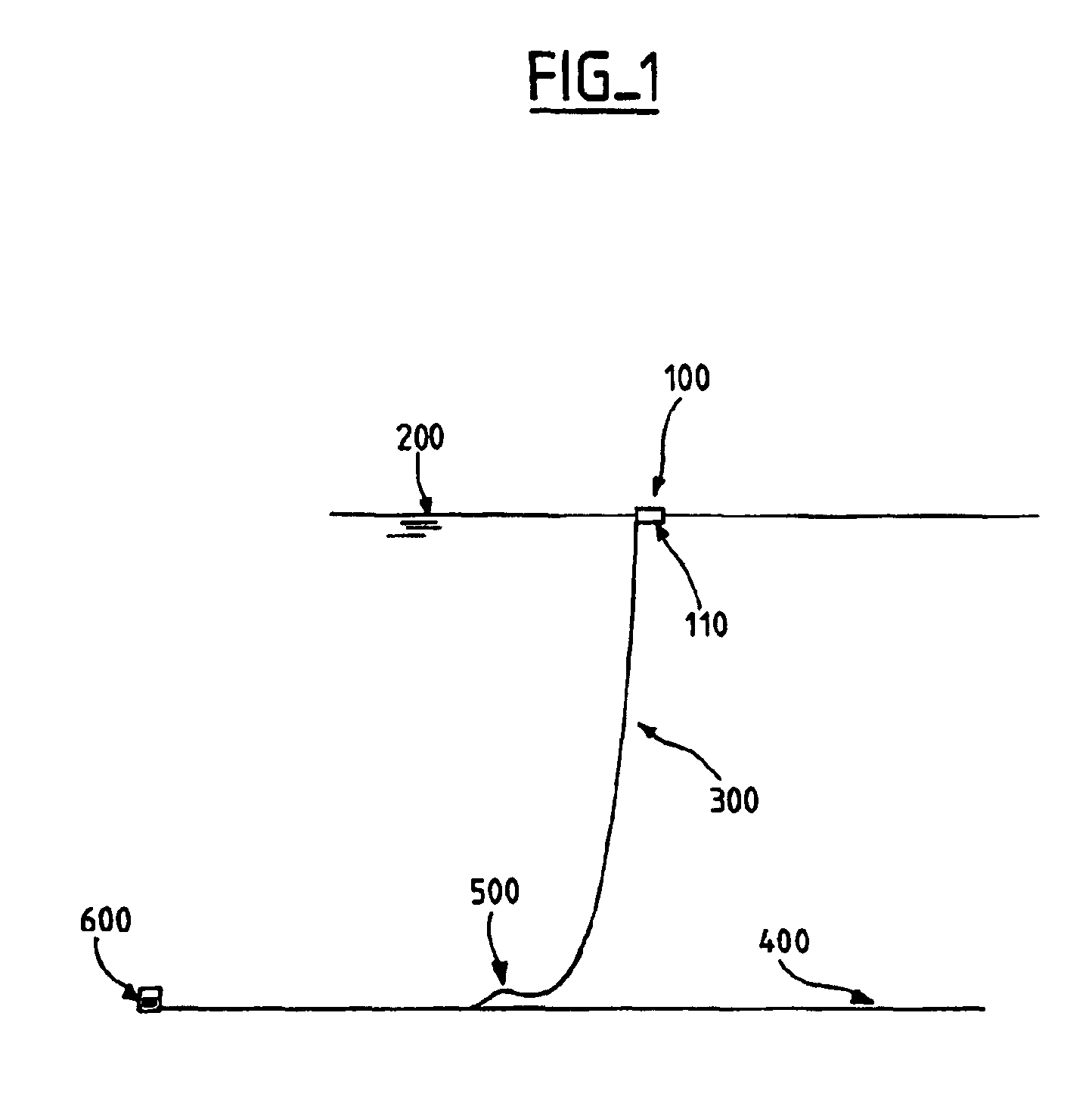
[0056]Such a cable 10 delivers power to a subsea system and is hanging freely suspended from a floating production vessel and down to the seabed. By way of example, such a cable 10 can replace the classical cable 300 shown in FIG. 1.

[0057]Starting from the center and moving radially to the periphery, around a longitudinal axis X, the power cable 10 comprises:[0058]an elongated load bearing component 1 including:[0059]an internal element 11 which is a rod suitable to carry high axial loads made of a axial stiffness material such as steel,[0060]and an polymeric layer 12 made of extruded crosslinked polyethylene and bonded around the rod 11, such a layer 12 including three helical grooves 13a-c on its external surface,[0061]three power conductor elements 2a-c intended to transport electrical energy, placed within one distinct groove 13a-c res...

second embodiment

[0081]FIG. 5a is a diagrammatic cross sectional view of an umbilical cable 30 which incorporates signal cable elements in the invention.

[0082]This dynamic umbilical cable 30 is hanging freely suspended from a floating production vessel and down to the seabed similar to what is illustrated in FIG. 1.

[0083]Starting from the center of the umbilical 30 and moving radially till the periphery, the umbilical cable 30 comprises:[0084]a central signal cable element 10′ forming a core,[0085]a first layer 31 of six other signal cable elements 10″ around said central element 10′,[0086]a protective wrapping 32,[0087]a second layer 33 of steel tubes 34,[0088]and outer covers 35 allowing entrance of sea water.

[0089]As shown in FIG. 5b, starting from the center and moving radially till the periphery, the signal cable element 10″ comprises:[0090]a load bearing component 1′ comprising:[0091]an internal element 11′ which is a steel tube containing hydraulic fluid delivered to a subsea control system,[...


PUM

PropertyMeasurementUnit
helical angleaaaaaaaaaa

Abstract

A flexible electrical elongated device is provided, suitable for service in a high mechanical load environment. The device has a longitudinal axis, and at least one elongated electrical conductor element. The device further has an elongated load bearing component along the longitudinal axis and has an external surface including at least one groove disposed along the longitudinal axis. The groove is designed for holding the conductor element within it while allowing the conductor element to move substantially radially when the device is bent.

Description

[0001]The present invention relates to flexible elongated electrical device suitable for service in a high mechanical load environment.FIELD OF THE INVENTION[0002]This application is related to and claims priority from Norwegian Patent Application No. 2003 3583, filed on Aug. 13, 2003, and Norwegian Patent Application No. 2003 4699, filed on Oct. 21, 2003, the entirety of which are incorporated herein by reference.BACKGROUND OF THE INVENTION[0003]The demand for electrical power supply at the sea floor increases with the increasing water depth at which oil production is being performed. This means that electrical energy must be supplied through power cables. These power cables have to hang freely suspended from the floating production vessel and down to the seabed, i.e. so-called dynamic cables.[0004]Copper is the most common metal used in electrical conductor element. Although having excellent electrical properties such as high conductivity, copper does not have mechanical propertie...

Claims


Application Information

Patent Timeline
Patent Type & Authority Patents(United States)
IPC IPC(8): H01B7/04H01B7/14
CPCH01B7/045H01B7/14D07B2201/2073D07B2201/2074D07B1/147D07B2201/2049D07B1/167
Inventor EKEBERG, KNUT IVAROTTESEN, TORFINN
Owner NEXANS
Why Eureka
Try Eureka