Vascular bypass grafting instrument and method

a vascular bypass and grafting technology, applied in the field of fasteners and delivery instruments, can solve the problems of localized death of living tissue, eventual failure of repair, and generally faster stapling, so as to reduce heart strain, reduce force requirements, and reduce blood loss. effect of loss

Inactive Publication Date: 2005-02-10
MILLER ARNOLD +1
View PDF0 Cites 44 Cited by
  • Summary
  • Abstract
  • Description
  • Claims
  • Application Information

AI Technical Summary

Benefits of technology

[0019] A still further object of the present invention is to provide an improved instrument and method for delivering a graft to the operative site, puncturing the aorta, and making an anastomosis quickly and reliably through a small incision, and with minimal loss of blood and reduced heart strain.
[0020] These objects of the invention are achieved by a surgical fastener preferably made from a shape memory alloy that accesses internal tissue or other synthetic material through a small surgical access port or incision. After the fastener is deployed through layers of tissue, it assumes a shape that automa

Problems solved by technology

Excess tension can cause necrosis (the localized death of living tissue) and eventual failure of the repair.
Furthermore, the application of staples requires that there be enough space for an instrument, which can produce the necessary force to form the staple against the anvil.
Stapling, however, is generally faster and, as previously noted, requires a lower level of skill.
Instruments developed for less invasive suturing, on the other hand, are slow and cumbersome and do not solve the essential problem of tensioning the suture and tying the knot remotely.
Suturing is feasible but difficult.
Conventional stapling is not feasible because an anvil cannot access the distal side of the tissue.
This fastener, however, does not produce compression upon the synthetic and natural tissue layers and thus does not produce hemostasis because the fastener is scre

Method used


Image

  • Vascular bypass grafting instrument and method
  • Vascular bypass grafting instrument and method
  • Vascular bypass grafting instrument and method

Examples


first embodiment

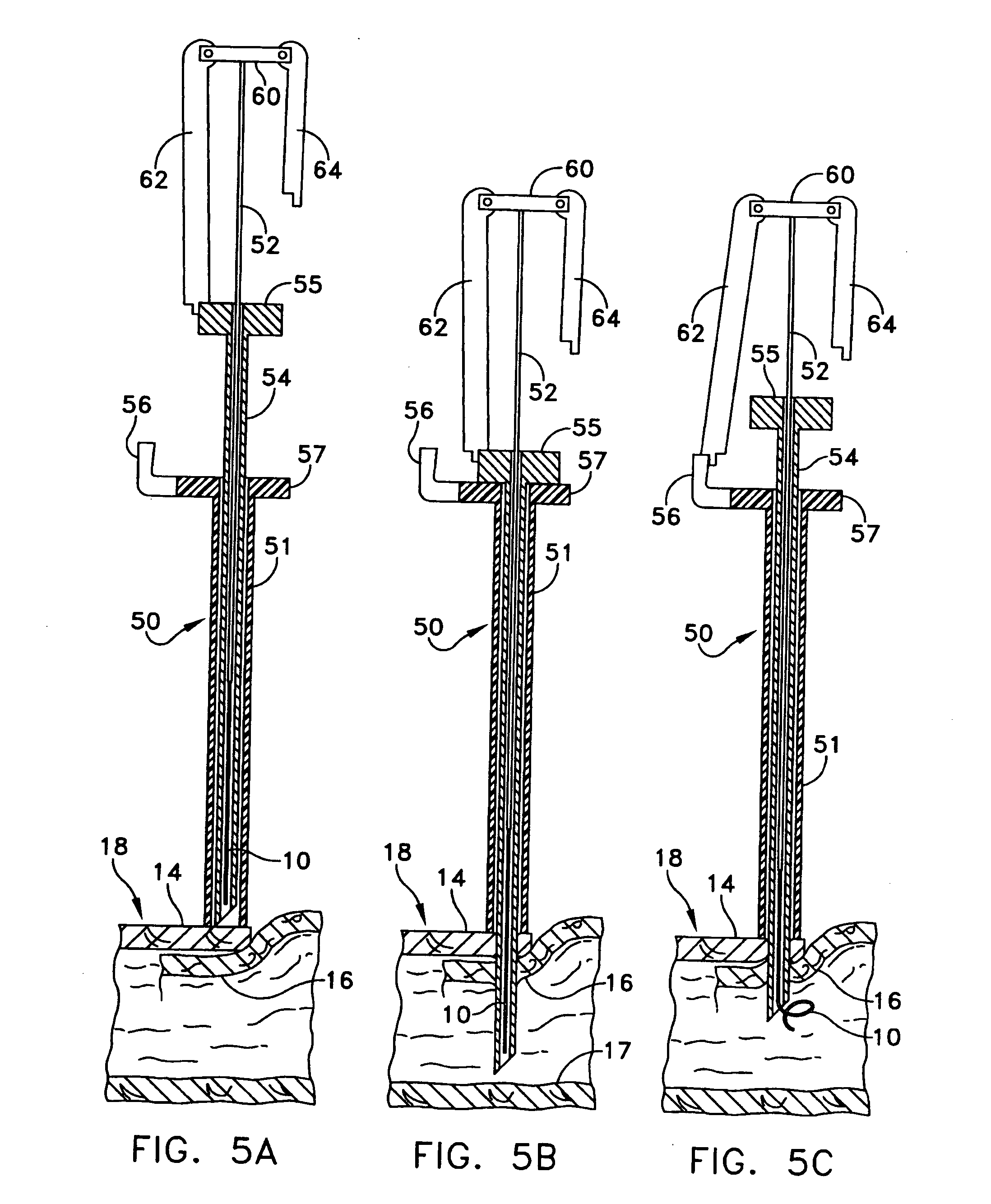
[0054]FIGS. 5A-5F show a delivery instrument 50 and the method for inserting the fastener. The delivery instrument 50 consists of a plunger 52 having a head portion 60, a needle 54 having a head portion 55, and a sleeve 51 having a head portion 57 and a stop 56. The plunger 52 fits slidingly inside a lumen of the needle 54, which fits slidingly inside of the sleeve 51. FIGS. 5A-5F show the fastener 10 being used to attach a graft (tissue; lower membrane) 16 to a blood vessel having a first layer of tissue 14 and an opposite wall 17. The fasteners described herein, however, can be used for any layers of material or tissue. Furthermore, the delivery instrument 50 can deliver any of the fasteners described herein.

[0055] Depending on the situation, support for the lower membrane 16 will be required in order to insert the fastener 10. This normally will be the rigidity of the body tissue itself or a mechanical support which is provided separately, often as an integral part of the instrum...

second embodiment

[0062]FIGS. 6A through 6F show the delivery instrument 100 which can deliver any of the fasteners described herein. The plunger 102 has a head portion 110 having both a short stop 114 and a long stop 112 attached to it. The head portion 105 of the needle 104 has two slots 116 and 118 to accept the long 112 and short 114 stops, respectively, at different times of the process. The needle 104 is slidingly accepted by sleeve 101 having a head portion 107. The tip of the delivery instrument 100, fastener 10 and needle 104 for FIGS. 6A-6F appear the same as in FIGS. 5A-5F, respectively, and are not shown for the sake of clarity.

[0063] First, as shown in FIG. 6A, the long stop 112 is brought into contact with the head portion 105 of the needle 104. The plunger 102 and needle 104 are then inserted into the tissue in unison by pushing down in the direction of arrow 120 until the needle's head portion 105 comes into contact with the sleeve's head portion 107, as shown in FIG. 6B. The needle 1...


PUM


Abstract

An instrument for attaching a graft to an aorta includes a first needle assembly for breaching the aorta to provide a hole in a wall thereof, and a carrier portion for insertion of an end of a tubular graft through the hole and into the aorta. Arms are pivotally mounted on the instrument and are moveable from a position extending axially of the carrier to a position extending radially from the carrier to spread the end of the graft radially outwardly from a tubular portion of the graft to form an annular flange extending outwardly from the tubular portion, and to support the flange within the aorta and around the hole therein. A second needle assembly retains the suture material and advances the suture material into engagement with the aorta wall and the graft flange for suturing the graft flange to the aorta wall.

Description

REFERENCE TO PENDING PRIOR PATENT APPLICATION [0001] This patent application claims benefit of pending prior U.S. Provisional Patent Application Ser. No. 60 / 229,675, filed Sep. 1, 2000 by William J. Allen et al. for VASCULAR BYPASS GRAFTING SYSTEM, which patent application is hereby incorporated herein by reference.FIELD OF THE INVENTION [0002] The invention relates to a fastener and a delivery instrument for joining multiple layers of thin flexible material. More particularly, the invention relates to a surgical fastener and a delivery instrument and method for joining living tissue and / or synthetic materials which may be used as a substitute for tissue. [0003] Still more specifically, the invention relates to a system for joining large grafts to the human aorta less invasively and with substantially less blood loss than is typically experienced in this type of operation. The invention further permits the graft to be anastomosed to the aorta without temporarily stopping the flow of...

Claims


Application Information

Patent Timeline
IPC IPC(8): A61B17/00A61B17/064A61B17/068A61B17/11
CPCA61B17/064A61B17/068A61B17/11A61B2017/1135A61B2017/0649A61B2017/1107A61B2017/00252
Inventor MILLER, ARNOLDALLEN, WILLIAM J.
Owner MILLER ARNOLD
Why Eureka
Try Eureka