Crane hoist apparatus

a crane and hoisting technology, applied in the field of cranes, can solve the problems of inefficient operation of loading and unloading containers, and consuming a fair amount of vertical space or headroom, and achieve the effect of minimising the loss of interior enclosure volum

Inactive Publication Date: 2006-05-23
WINDBERGS WERNER J
View PDF2 Cites 37 Cited by
  • Summary
  • Abstract
  • Description
  • Claims
  • Application Information

AI Technical Summary

Benefits of technology

[0006]It is an object of the present invention to provide a new and useful crane hoist apparatus and method for use in moving items within an interior of a containerized cargo enclosure with the result of a minimal loss of interior enclosure volume from the crane.
[0009]Still another object of the present invention to have the first frame that is adapted to attach to the interior of the containerized cargo container with a slidable support that allows the first frame to movably extend from between a first retracted position in an interior of the containerized cargo enclosure to a second extended position in which the first frame extends to an exterior of the containerized cargo enclosure allowing for the winch carriage to reach selected locations on the exterior of the containerized cargo enclosure to move items.
[0010]According to the present invention, then, a crane hoist apparatus and method for use is provided in moving items within, into, out of, and adjacent or exterior to an interior of a containerized cargo enclosure is disclosed with the result of a minimal loss of interior enclosure volume from the crane. Broadly, the present invention includes a first frame having a plurality of beams that each include a lengthwise span, a width, and a depth, with the first frame being adapted to be supported by the containerized cargo enclosure. Also included, is a second fame having a beam with a lengthwise span, a width, and a depth, with the second frame being slidably supported by the first frame in an approximately transverse span orientation such that the second frame depth does not extend below the first frame depth. The second frame is able to move in a direction parallel to the first frame span. In addition, a winch carriage is included that is slidably supported by the second frame such that the winch does not extend below the second frame depth, with the winch being able to move in a direction parallel to the second frame span.

Problems solved by technology

However, when the containers are loaded with many small items that are not necessarily light in weight, being within the 50 lb. to 1,000 lb. range, loading and unloading the container can become an inefficient operation due to the manual handling of these numerous items.
Both Kucharczyk et al. and Dunbar recognize one of the problems in the art in using this type of crane is that the normal crane construction of what is called the trolley or bridge type of crane dictates that the frames are mounted one below the other with the resulting winch carriage being mounted below the lowest frame.
Also, this type a crane in its usual mounting location, which would either be a warehouse or factory, typically has extra high ceilings that can allow for this type of crane construction, which consumes a fair amount of vertical space or headroom.
When utilizing a crane hoist apparatus within a cargo container, however, this consumption of vertical space or headroom is a negative factor in mounting a specialized crane apparatus inside of a cargo container, and thus design modifications need to be made to the crane frames and winch to minimize the vertical distance or headroom consumed.
However, when a crane is designed to absolutely minimize the vertical distance consumed or headroom there are compromises of the cranes weightlifting capacity when the frame beams are loaded in the same horizontal plane that induces a torsional moment component into the beam loading, wherein any given beam has considerably less strength when placed in a torsional loading state as opposed to a straight vertical load state.
Thus, to minimize the consumption of vertical space or headroom there has to be a number of considerations in the slidable engagements between the frames and the carriage winch, in addition to a more difficult task of calculating the much reduced load carrying capacity of a crane constructed in this manner.

Method used


Image

  • Crane hoist apparatus
  • Crane hoist apparatus
  • Crane hoist apparatus

Examples


Embodiment Construction

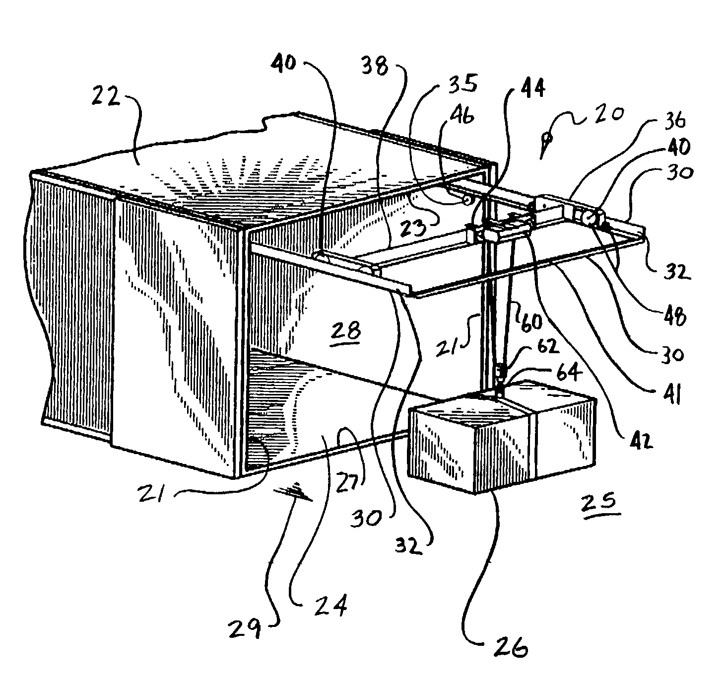
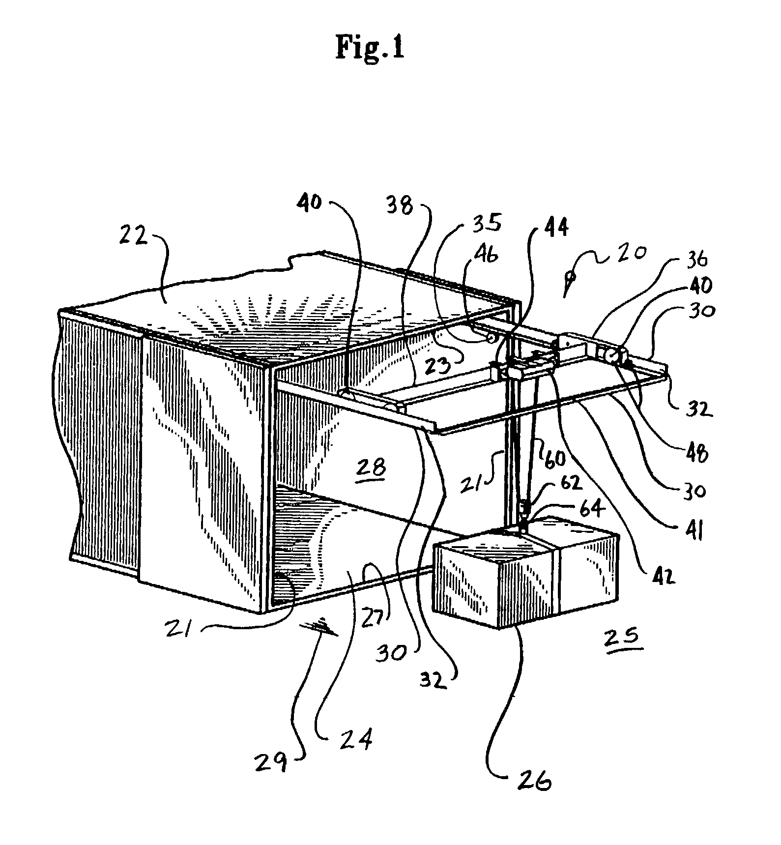
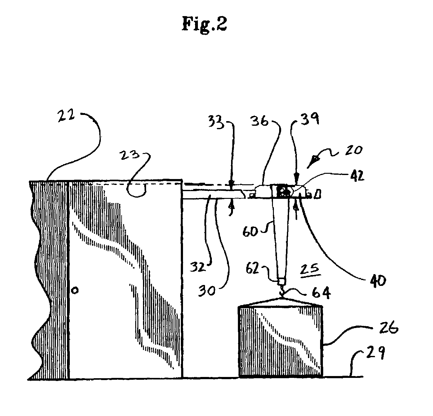
[0059]With initial reference to FIG. 1, FIG. 2, and FIG. 3 shown is a perspective view of the crane hoist apparatus assembly 20 in use lifting the item 26 adjacent to the containerized cargo enclosure 22, a side elevation view of the crane hoist apparatus assembly 20 in use lifting the item 26 adjacent to the containerized cargo enclosure 22, and a perspective view the crane hoist apparatus 20 respectively. FIGS. 1 and 2 show the first frame 30 in a second extended position to an exterior 25 to relative to the enclosure 22. Although the crane hoist apparatus assembly 20 shows the item 26 being lifted adjacent to the containerized cargo enclosure 22, the crane hoist apparatus assembly 20 is fully capable of retracting completely within the enclosure 22 to allow for placing the item 26 at a selected location within the interior volume 28 in the interior 24 of the enclosure 22. This ability of the first frame 30 to go to a first retracted position in the enclosure 22 by utilizing a sli...


PUM


Abstract

A crane hoist apparatus and method of use for moving items within, into, out of, or adjacent to an interior of a containerized cargo enclosure causing minimal loss of interior enclosure volume from the crane. The crane includes a first frame with a plurality of beams each having a span, a width, and a depth, the first frame is supported by the enclosure, also a second frame having a beam with a span, a width, and a depth, that is slidably supported by the first frame in a transverse span orientation, with the second frame depth not extending below the first frame depth, the second frame moves in a direction parallel to the first frame span. A winch carriage is slidably supported by the second frame wherein the winch does not extend below the second frame depth, the winch moving in a direction parallel to the second frame span.

Description

TECHNICAL FIELD[0001]The present invention generally relates to cranes for the purpose moving items and more particularly to special purpose cranes for operation within a containerized cargo enclosure to move items both within the enclosure and exterior to the enclosure. The present invention addresses this situation by having a crane that is adapted to be supported by the enclosure with the crane contained within the enclosure and causing a minimal loss of interior enclosure volume from the crane apparatus.BACKGROUND OF INVENTION[0002]Containerized cargo has become ever more popular in recent years as a very efficient means of shipping a multitude of items or goods. Standard size containerized cargo enclosures are utilized on special ships that hold a numerous of these types of containers in a stacked arrangement on special container ships. These containers are carried both within the hull or container hold of the container ship and above the deck of the container ship with the con...

Claims


Application Information

Patent Timeline
Patent Type & Authority Patents(United States)
IPC IPC(8): B60P1/54B66C9/08B66C9/10B66C17/00B66C23/20
CPCB66C9/08B66C23/206B66C17/00B66C9/10
Inventor WINDBERGS, WERNER J.
Owner WINDBERGS WERNER J
Why Eureka
Try Eureka