[0041](b) uses a steady-state magnetic field geometry with minimum losses; e.g., a “mirror”
type system without line or ring cusps—its cusps are all point cusps. The geometries of interest utilize special polyhedral configurations for magnetic field generating means. These configurations all have the property that there is always an even number of faces around every vertex of the polyhedron, thus ensuring that alternate faces have opposite magnetic polarities, when the fields are produced by conductors located on or near to the edges of the polyhedron spatial surface. In addition, oscillation of single polyhedral or multiply-faceted interlaced polyhedral surface fields may be useful to provide good magnetic surface “reflection” of confined electrons, by causing the time-averaged fields to appear “quasi-spherical” over the electron
gyration time at the
local field strength, although such time-varying fields are not essential to the present concept.
[0042](c) uses magnetic field coils whose containing structures are conformal to the shape of the fields they produce, so as to avoid any “corners” or exposed
metal surfaces through which field lines can pass directly and thus constitute loss channels for
electron loss from the system. Further to space all coil containers at a distance from each other (i.e., so that they do not touch) at the corners of the polyhedral configurations, so that the magnetic fields produced can flow freely between the adjacent coils, without intersecting the surfaces of the coil containers. This spacing is preferably about 3-10 gyro radii in dimension and more preferably about 3-8 gyro radii. Larger gyro radii are not desired to avoid excessive loss of interior
trapping of electrons by the main coil system fields, and consequent excessive reduction of Gwb from the levels desired to ensure high interior electron densities. It is generally desirable that no B fields intersect any metal surfaces in the system to avoid electron losses. The conformal structures described herein permit effective shielding of the B fields, and it is generally desirable that most surface be shielded, i.e., optimally less than 1 / 10,000 of all surfaces are unshielded.
[0057]When operated in such a pulsed or oscillatory mode, nuclear-reaction-generated energy may be coupled into oscillations of the confined
plasma, itself, to yield amplification of the pulsations and thus to yield
high frequency radiative
power output, or to yield oscillation of surface potentials on the container walls surrounding the plasma region, and thus to surface (spherical) wave generation. By this means the device can become a self-amplifying, self-powered generator of
microwave or other radio-frequency energy. If operated with
electron injection currents,
ion densities, and magnetic fields which allow large
power gain to occur, such a device can be used as a powerful source of radio-frequency energy, for
radar, communications, power-beaming, energy beam weapons, etc., with no
external source of main power.
[0059]According to certain embodiments, at the onset of fusion reactions in the device, the fusion product ions will escape from the system, leaving behind their electrons, to yield a still-more-negative confining well. This could lead to a “runaway” effect in which continuing reactions yielding fusion products create an ever-deepening well, which in turn increases the
fusion rate, which deepens the well more, etc. This process will be stopped by
burnout of the ion fuel in the well, by arcing or other “shorting” or destabilizing effects, or by reaching stable burn conditions in balance with the ion and
electron injection rate, and the rate of escape of electrons and of ions from the surface of the confinement region (i.e., from the magnetic field). The nature of this self-initiated creation of deeper potential wells will depend upon the species of ions used in the device, and undergoing fusion reactions. If all the ions involved carry only single nuclear charges (i.e., if all have only one
proton in the
nucleus), then the onset of fusion reactions can lead to a well-deepening effect, as described above, only for a limiting transient period. This transient will be damped out by the
continuous injection of new electrons and ions, to reach a new stable
density distribution. However, if the ions involved carry more than one
proton in their
nucleus and are injected only partially stripped, with a single charge, then the onset of fusion will trigger an exponential well-deepening process stabilizing at a new, deeper well depth as a result of each fusion reaction leaving more electrons behind in the well than were originally injected.
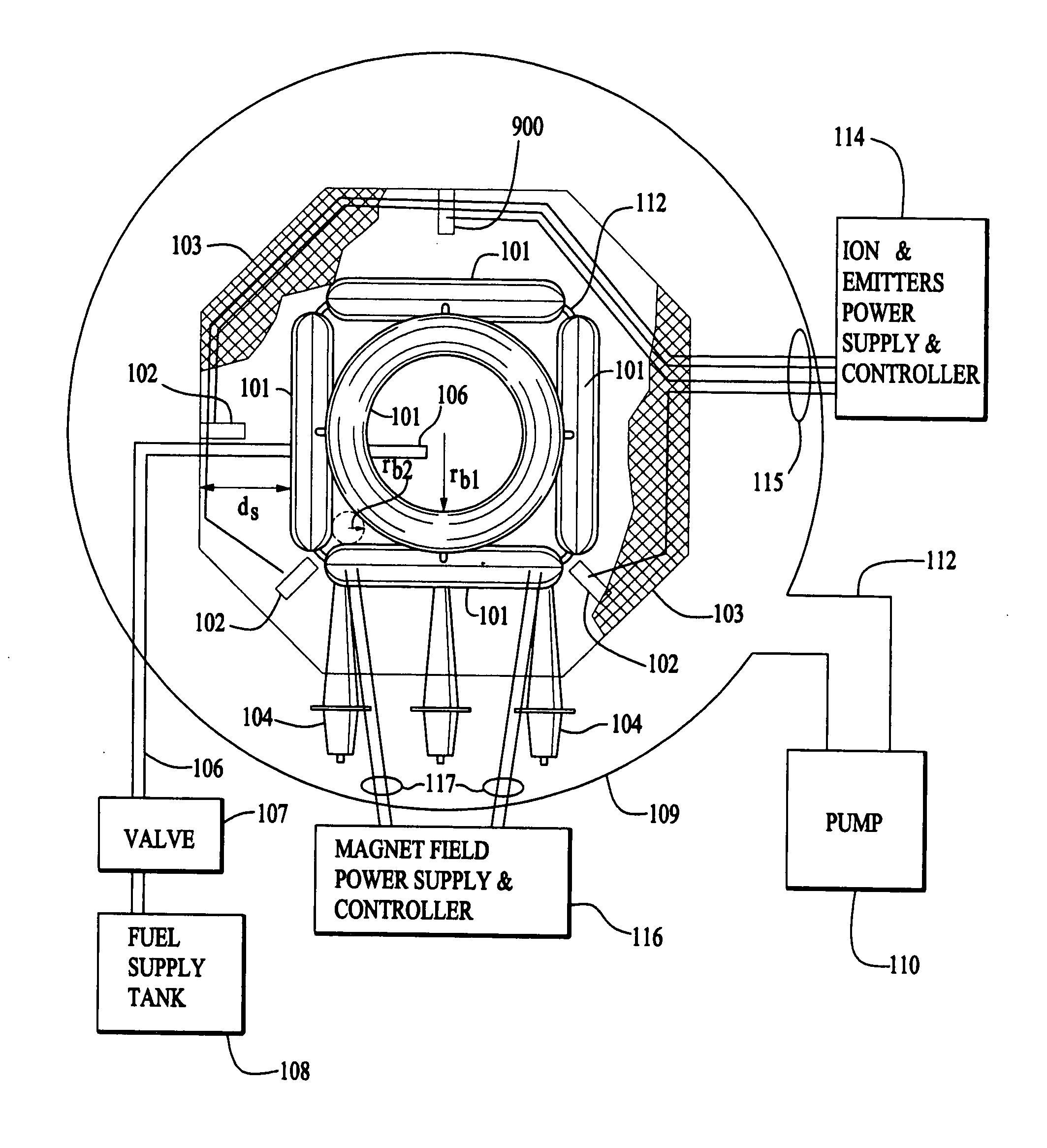
[0070]For example, a typical coil system for a truncated-cube polyhedral configuration as, for example, shown in FIG. 8, would be a set of six coils, square in plan form, of circular cross-section, with conductors within the circular containers, each laid slightly offset from the edges of the polyhedron, so that their corners (i.e., edges of the polyhedral) do not touch, but are spaced at (e.g.) 5 electron gyro radii from each other. The coils are held together by metal connecting tubes connecting each coil to its adjacent coils at the corners of the polyhedral, with the connecting tubes located well outside the mid-plane of the coil systems, so as to be in regions of
electron density which are lower density than those in the interior of the
machine, thus reducing electron losses to these relatively unshielded metal surfaces. Some degree of shielding can be provided if the conductors within the coils also connect from coil to coil by conductors running through the connecting tubes. In this case, the connecting tubes would provide stability of the coil structures by joining them mechanically together and would provide a conduit for electrically connecting each coil to the power source since all coils would be connected together in series.
[0071]According to another feature of the invention, embodiments may utilize a finite coil in which connected coils are replaced with coils with gaps between them. Preferably, the coils are placed on the outboard side of the confining coils. As described below, this feature dramatically increases electron confinement. The
power output is set by the rate of reaction within the
central region, integrated over the volume of this region. The
reaction rate is determined by the square of the
ion density (and the product of reaction cross-section and particle speed), thus is limited by the
ion current density in the
central region. In-falling ions will converge as the inverse square of the
radius, thus the
reaction rate will tend to vary as the inverse fourth power of the
radius. This very rapid dependence ensures that nearly all of the fusion energy generated in such a device will be generated in and around the center of the (structurally-empty) cavity confined by the external magnetic field, at the largest possible distance from the walls of the system. It will be somewhat like a little “star” burning in the center of the electrostatic well cavity “void”.

