Hydrodynamic bearing device

a technology of bearing device and bearing shaft, which is applied in the direction of bearings, shafts and bearings, rotary bearings, etc., can solve the problems of inability to efficiently gather lubricating fluid to a central portion, inability to keep predetermined groove depth, and inability to efficiently collect lubricating fluid, etc., to achieve the effect of reducing cost, broadening the margin for bearing design, and improving reliability of dynamic pressure bearings

Active Publication Date: 2007-03-29
PHC HLDG CORP
View PDF6 Cites 3 Cited by
  • Summary
  • Abstract
  • Description
  • Claims
  • Application Information

AI Technical Summary

Benefits of technology

[0059] According to the hydrodynamic bearing device of the present invention, a reliability of the dynamic pressure bearing is improved, a margin for designing the bearing is broadened and the cost can be reduced by stabilizing the balance of dynamic pressures generated at the thrust bearing portions all the time.

Problems solved by technology

However, the above conventional hydrodynamic bearing devices have the following problems.
Specifically, in the structure of the thrust dynamic pressure bearing disclosed in Japanese Laid-Open Publication No. 2000-346056, there is a possibility that a predetermined groove depth cannot be kept due to metal-to-metal contact of a thrust surface with an opposing surface when the motor, and, in turn, the bearing starts to rotate, or the like.
Thus, a lubricating fluid cannot be efficiently gathered to a central portion in the radial direction of the dynamic pressure generating grooves.

Method used


Image

  • Hydrodynamic bearing device
  • Hydrodynamic bearing device
  • Hydrodynamic bearing device

Examples


Embodiment Construction

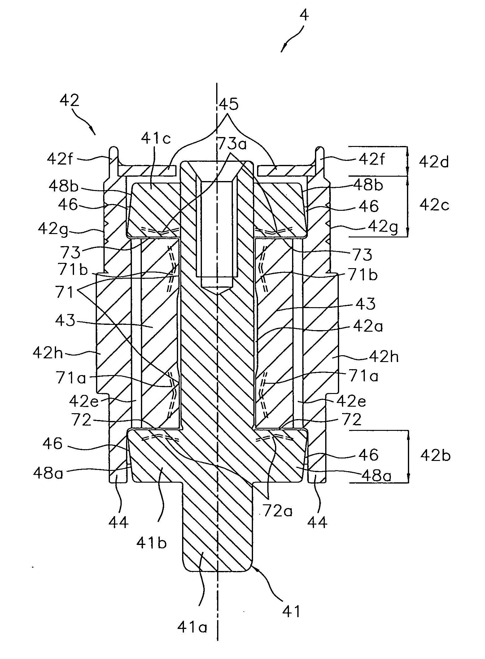
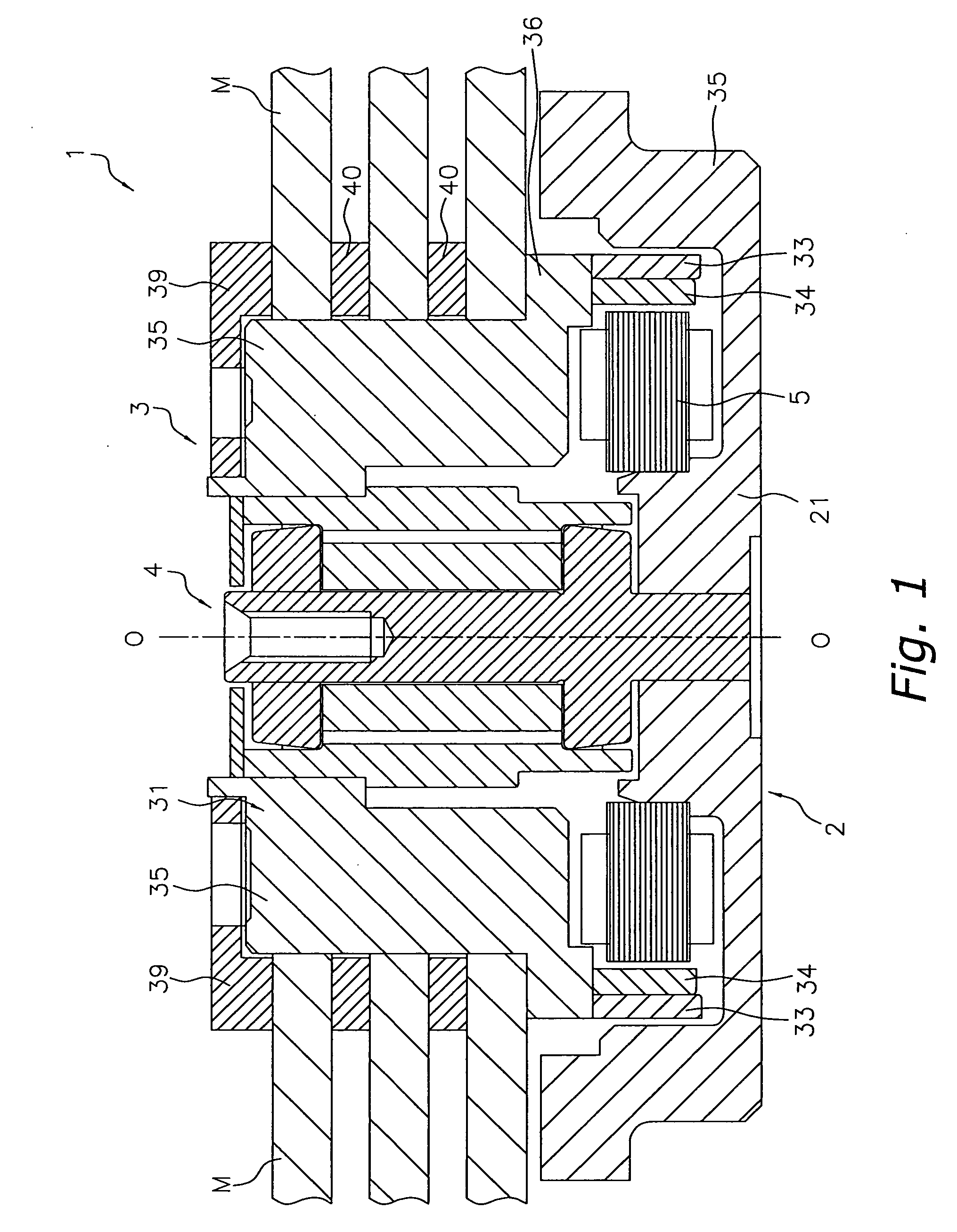
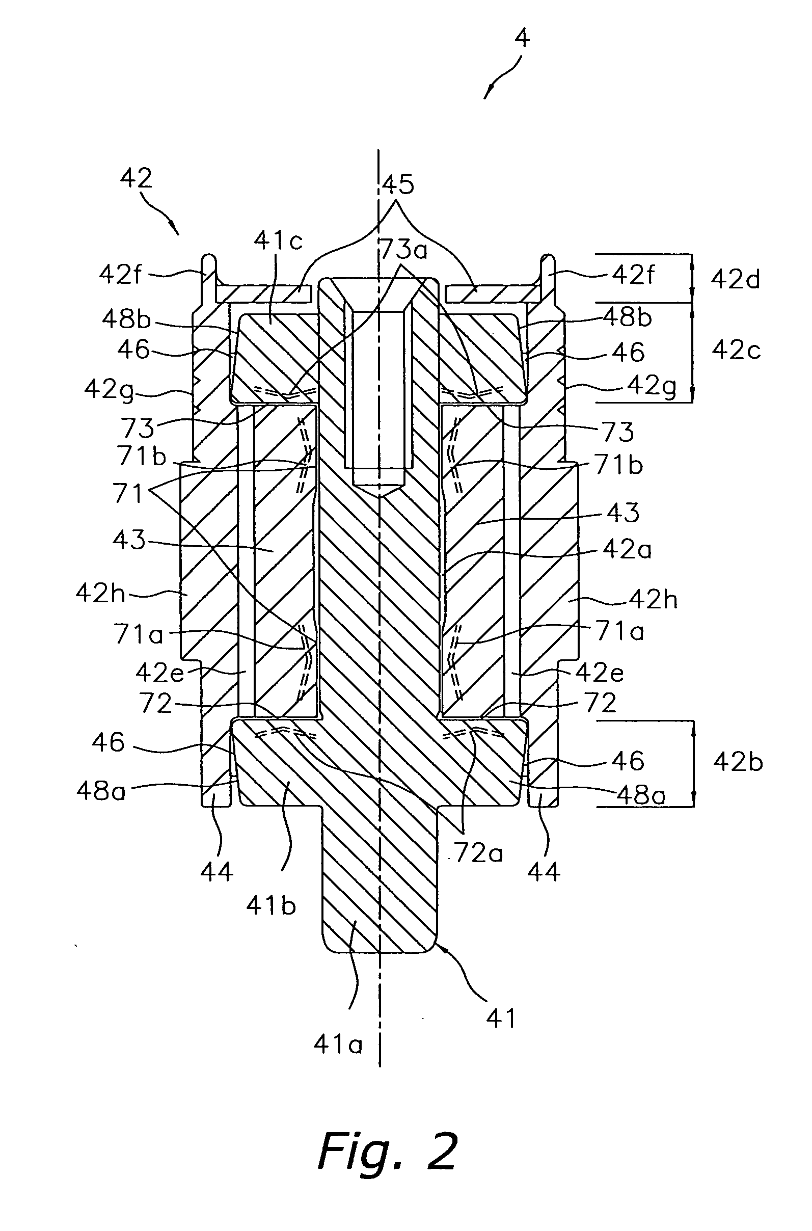
[0075] A spindle motor 1 including a hydrodynamic bearing device according to an embodiment of the present invention is described as follows with reference to FIGS. 1 through 10.

[0076] In the present embodiment, a vertical direction in the figures are referred to as “upper side in the axial direction”, “lower side in the axial direction”, and the like for the convenience of explanation. However, such expressions are not intended to limit how the spindle motor 1 is actually integrated.

[Entire Structure of the Spindle Motor 1]

[0077] As shown in FIG. 1, the spindle motor 1 includes, mainly, a base 2, a stator 5, a rotor 3, and a hydrodynamic bearing device 4. Line O-O shown in FIG. 1 is a rotational axis line of the spindle motor 1.

[0078] The base 2 includes a cylinder-shaped portion 21, and one end of a shaft 41 (see FIG. 2) of the hydrodynamic bearing device 4 is fixed to an inner periphery of the cylinder-shaped portion 21.

[0079] The rotor 3 is a member of a rotating part of th...


PUM


Abstract

A hydrodynamic bearing device which can improve reliability by stabilizing a balance of dynamic pressures generated at a thrust bearing portion. The spindle motor 1 includes a hydrodynamic bearing device 4 including a shaft 41, a sleeve 42, first and second thrust flanges 41b and 41c, first and second thrust bearing portions 72 and 73 and thrust dynamic pressure generating grooves 72a and 73a. The thrust dynamic pressure generating grooves 72a and 73a are formed such that a plurality of groove portions are connected without being isolated from each other, and the groove depth becomes greater from the inner periphery toward the outer periphery.

Description

TECHNICAL FIELD [0001] The present invention relates to a hydrodynamic bearing device having a thrust dynamic pressure bearing portion. BACKGROUND ART [0002] Conventionally, hydrodynamic bearing devices having a thrust dynamic pressure generating portion formed on a surface of either a sleeve or a shaft have been used. In the thrust dynamic pressure generating portion, a dynamic pressure is generated by rotating the sleeve or the shaft which is a rotating part to rotate the rotating part in a non-contact state, which means that a predetermined space is interposed therebetween. [0003] For example, Japanese Laid-Open Publication No. 2000-346056 discloses a thrust dynamic pressure bearing having a plurality of dynamic pressure generating grooves formed on an end surface of a flange formed on an end surface of the shaft. The dynamic pressure generating grooves having a herringbone pattern, and are formed with a predetermined gap interposed among them in a circumferential direction. [000...

Claims


Application Information

Patent Timeline
Patent Type & Authority Applications(United States)
IPC IPC(8): F16C32/06
CPCF16C17/045F16C33/107F16C17/107
Inventor HAGA, TOMOHIRONAKAMURA, JUNICHI
Owner PHC HLDG CORP
Why Eureka
Try Eureka