Paddle-type flowmeter with magnetic coupling

a flowmeter and magnetic coupling technology, applied in the field of flowmeters, can solve the problems of insufficient actuating force, rotatable shaft, and inability to adjust the axial direction, and achieve the effect of increasing dynamic pressure and minimizing the influence of any turbulent flow

Active Publication Date: 2013-03-19
MASCHFAB REINHAUSEN GEBR SCHEUBECK GMBH & CO KG
View PDF15 Cites 3 Cited by
  • Summary
  • Abstract
  • Description
  • Claims
  • Application Information

AI Technical Summary

Benefits of technology

[0011]According to another advantageous embodiment, the paddle is constructed as a cup-shaped upstream-open flow body, similar to a spoon, which at the same time minimizes the influence of any turbulent flow in the pipe because increased dynamic pressure is able to build up upstream of the paddle.

Problems solved by technology

On the one hand, they tend to jam in their final positions for different reasons.
This is often due to the fact that the mount is inadequate, the rotatable shaft is twisted, or the actuating force is not sufficient by virtue of the construction of the flowmeter.
Moreover, the known flowmeters are sensitive to the turbulence often produced by pumps, such that the display wobbles or the necessary force for moving the display is not sufficient.

Method used


Image

  • Paddle-type flowmeter with magnetic coupling
  • Paddle-type flowmeter with magnetic coupling
  • Paddle-type flowmeter with magnetic coupling

Examples


Embodiment Construction

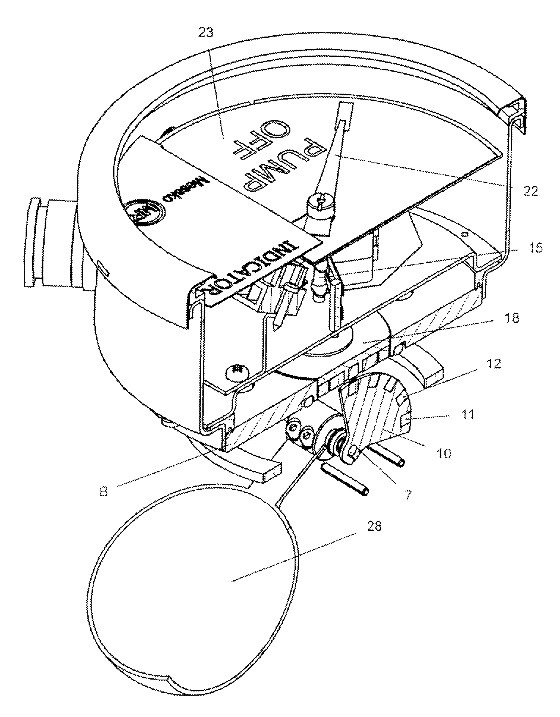
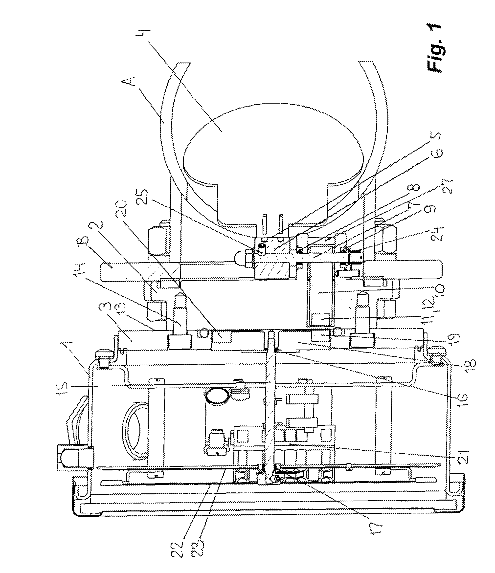
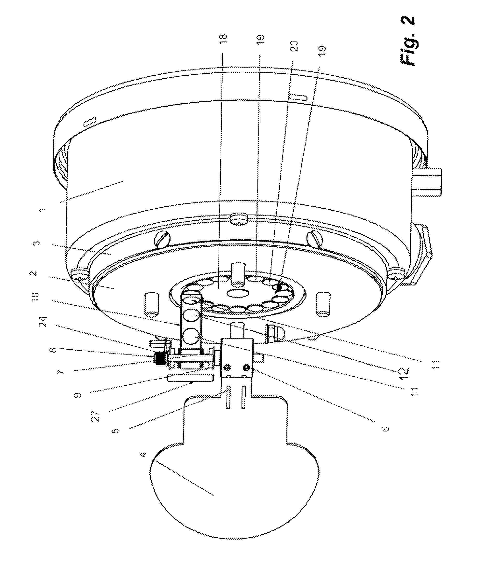
[0020]First, the construction shown in FIG. 1 shall be described.

[0021]A flowmeter according to the invention intended to monitor the flow in a pipe A is bolted to a flange B of this pipe A provided especially for this purpose.

[0022]The flowmeter itself comprises a housing 1 and a mounting plate 2 bolted to it. To this end, a flange 3 to which the mounting plate 2 mentioned above is bolted is provided on the housing 1. A paddle 4 is pivotally mounted on the plate 2. To this end, the paddle 4 is formed with a bar 5 to which a bracket 6 is attached. This bracket 6 and therefore the paddle 4 are fixed to a rotatable shaft 7. The shaft 7 is supported on the mounting plate 2 by bearings 8 and 9. A sector plate 10 having an is circularly arcuate outer edge is attached in turn to the rotatable shaft 7. Magnets, specifically N magnets 11 alternating with S magnets 12 polarized radially to the mounting plate 2 and thus to the flange 3, are fitted to the edge of the sector plate 10.

[0023]As d...


PUM


Abstract

The invention relates to a flow monitor for monitoring the flow of flowing media, wherein a paddle projecting into the flow transfers the rotating movement of the paddle onto a display device by means of a magnetic gear comprising a plurality of individual magnets corresponding with each other.

Description

CROSS REFERENCE TO RELATED APPLICATIONS[0001]This application is the US national phase of PCT application PCT / EP2009 / 000649, filed 31 Jan. 2009, published 24 Sep. 2009 as 2009 / 115162, and claiming the priority of German patent application 102008015158.0 itself filed 20 Mar. 2008, whose entire disclosures are herewith incorporated by reference.FIELD OF THE INVENTION[0002]The invention relates to a flowmeter for monitoring fluids in pipes, in particular for monitoring the flow and thus the pump function of cooling systems on electric transformers.BACKGROUND OF THE INVENTION[0003]Such flowmeters are known in numerous embodiments. DE 3,317,923 describes such a flowmeter, termed a flow switch, that has a paddle projecting into the fluid flow to be monitored. A pivotal rod carrying the paddle has a free end carrying a permanent magnet that cooperates with a Reed switch. Thus, like numerous other similar flowmeters, this paddle forms in the flow a flow resistance. If the flow level is suff...

Claims


Application Information

Patent Timeline
Patent Type & Authority Patents(United States)
IPC IPC(8): G01F1/115G01F1/28
CPCG01F1/28
Inventor BRILL, REINERHAEMEL, KAIREHNELT, ULRICHVIERECK, KARSTEN
Owner MASCHFAB REINHAUSEN GEBR SCHEUBECK GMBH & CO KG
Why Eureka
Try Eureka