

Golf club head with adjustable center of gravity
- Summary
- Abstract
- Description
- Claims
- Application Information
AI Technical Summary
Benefits of technology
Problems solved by technology
Method used
Image

Examples
first embodiment
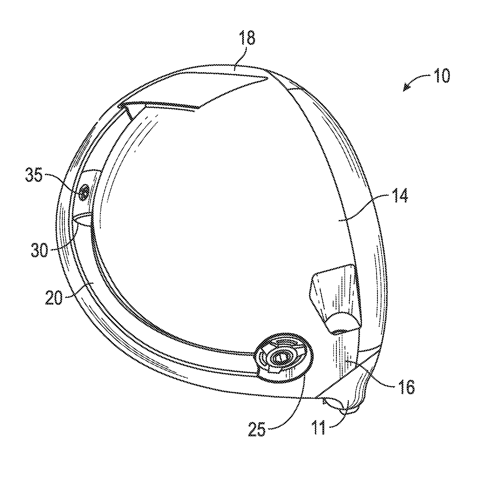
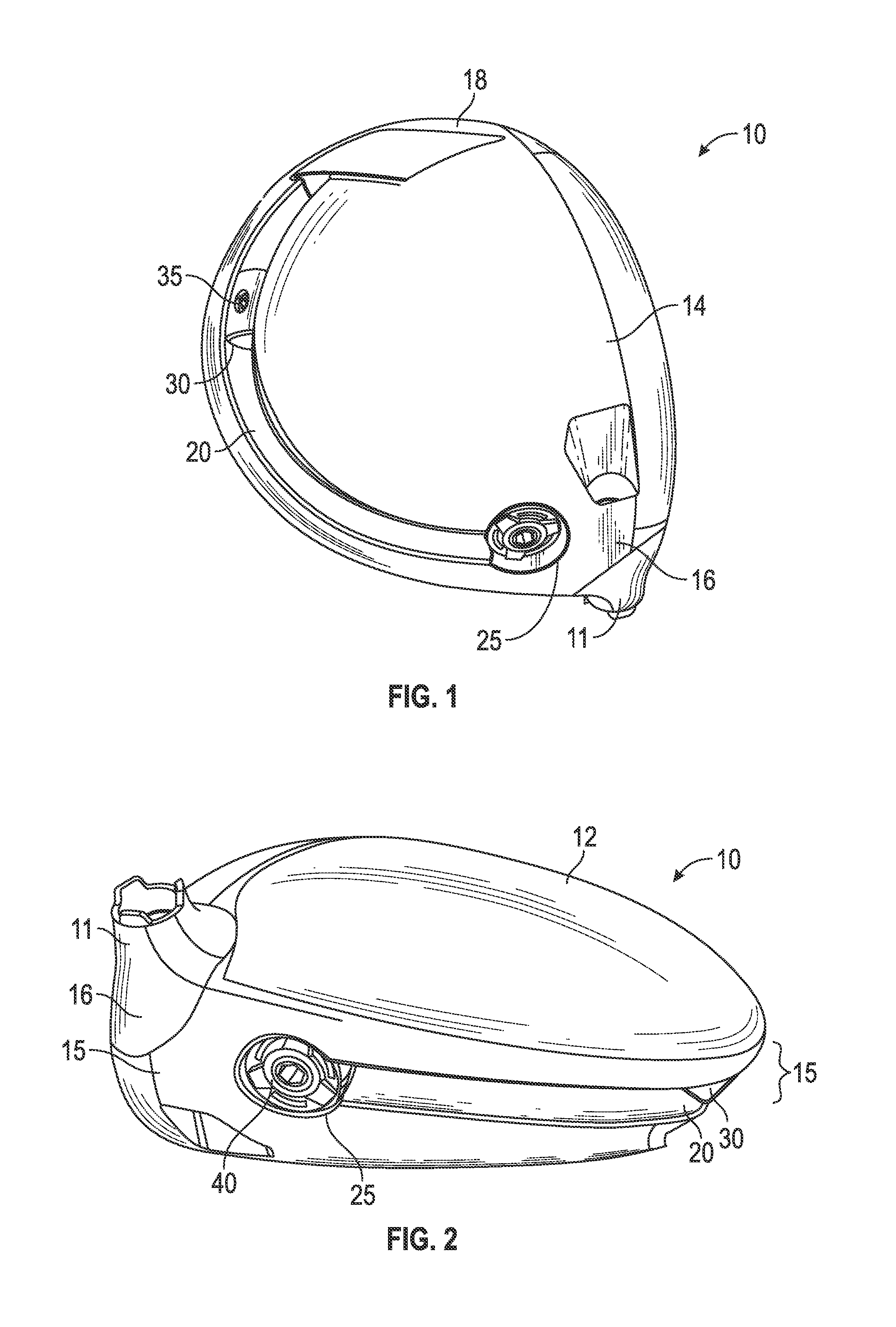
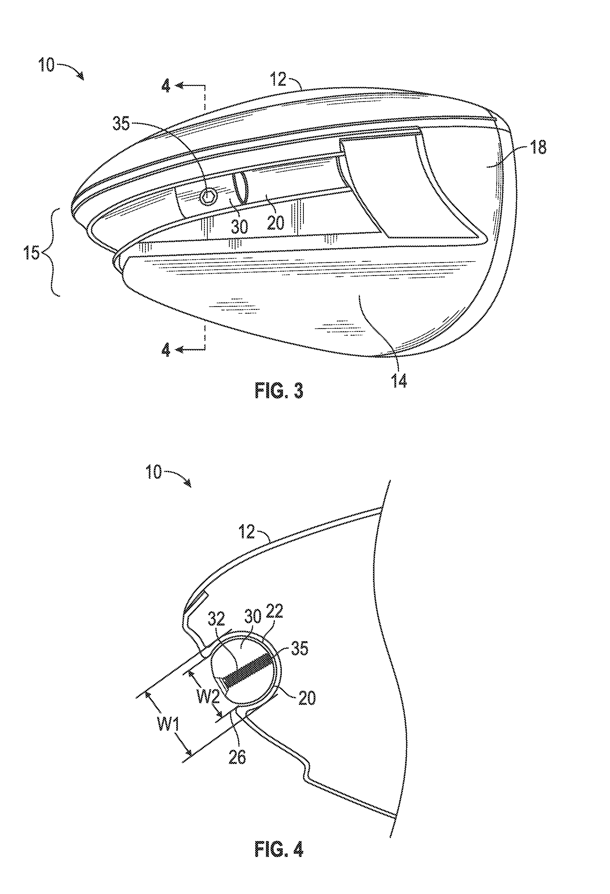
[0043]the present invention is shown in FIGS. 1-4. The golf club head 10 comprises a channel 20 disposed within a side or ribbon 15 portion of the golf club head 10, but may in alternative embodiments may be disposed in the crown 12 and / or sole 14. The channel 20 extends from a heel side 16 of the club head proximate a hosel 11 to a toe side 18 of the golf club head 10, and has a curved cross-sectional shape with an internal width W1 that is greater than an external opening width W2. The channel 20 may have any of the configurations disclosed in U.S. patent application Ser. No. 13 / 656,271, the disclosure of which is hereby incorporated by reference in its entirety herein.
[0044]A slidable weight 30 is disposed within the channel 20, and is inserted into the channel 20 at an opening 25 proximate the heel 16, which is closed with a weight screw 40 or a lightweight plug once the slidable weight 30 is inserted into the channel 20. The weight screw 40 or plug and slidable weight 30 can be...
fifth embodiment
[0050]the present invention is shown in FIGS. 16-18. This embodiment is similar to the one shown in FIGS. 5-11, but includes a three-piece slidable weight 200 instead of a two-piece slidable weight 50, and the various pieces of the three-piece slidable weight 200 are obscured from view when the slidable weight 200 is disposed within the channel 250 of the golf club head 10. The three-piece slidable weight 200 of the preferred embodiment is also similar to the embodiment shown in FIGS. 4 and 15, in that the bolt 220 makes contact with the floor portion 255 of the channel 250 instead of a portion of the slidable weight 200 when the three-piece slidable weight 200 is fixed within the channel 250.
[0051]In the fifth embodiment, the slidable weight 200 includes an upper portion 205 composed of a durable metal material, preferably 17-4 stainless steel, a middle portion 210 composed of a lightweight, expandable material, preferably injection-molded plastic or rubber, and a lower portion 215...
PUM
 Abstract
Description
Claims
Application Information