Slidable Weight Assembly

a weight assembly and sliding technology, applied in the field of sliding weight assemblies, can solve the problems of not optimizing weight adjustment, achieve the effect of maximizing aesthetic appearance, facilitating movement and fixing weights, and preserving the function of movable weights

Active Publication Date: 2016-10-20
TOPGOLF CALLAWAY BRANDS CORP
View PDF8 Cites 0 Cited by
  • Summary
  • Abstract
  • Description
  • Claims
  • Application Information

AI Technical Summary

Benefits of technology

[0007]The present invention is a novel way of working with adjustable products. The present invention allows consumers to easily move and fix a weight at any location within a channel disposed in a piece of sporting goods equipment, and particularly a golf club head, in such a way to maximize aesthetic appearances while preserving the function of the movable weight. The objective of this invention is to provide an adjustable weight with minimal or no effect on appearance at address while maximizing the ability of the weight to adjust center of gravity height. Additional goals include minimizing the fixed component of the structure dedicated to the weighting system and also minimizing any potential effect on impact sound. Yet another object of the present invention is an adjustable weighting feature for lateral or vertical center of gravity control which is placed to maximize effectiveness and may be entirely concealed from view at address.
[0008]One aspect of the present invention is a slidable weight comprising a clamping mechanism with a cam feature that, when turned 90 degrees, causes a combined clamping and pull-down effect that fixes the weight within a channel, which may be disposed in any sporting equipment but particularly in a golf club head.

Problems solved by technology

The prior art includes several different solutions for adjustable weighting, but these solutions do not optimize weight adjustment.

Method used


Image

  • Slidable Weight Assembly
  • Slidable Weight Assembly
  • Slidable Weight Assembly

Examples


Embodiment Construction

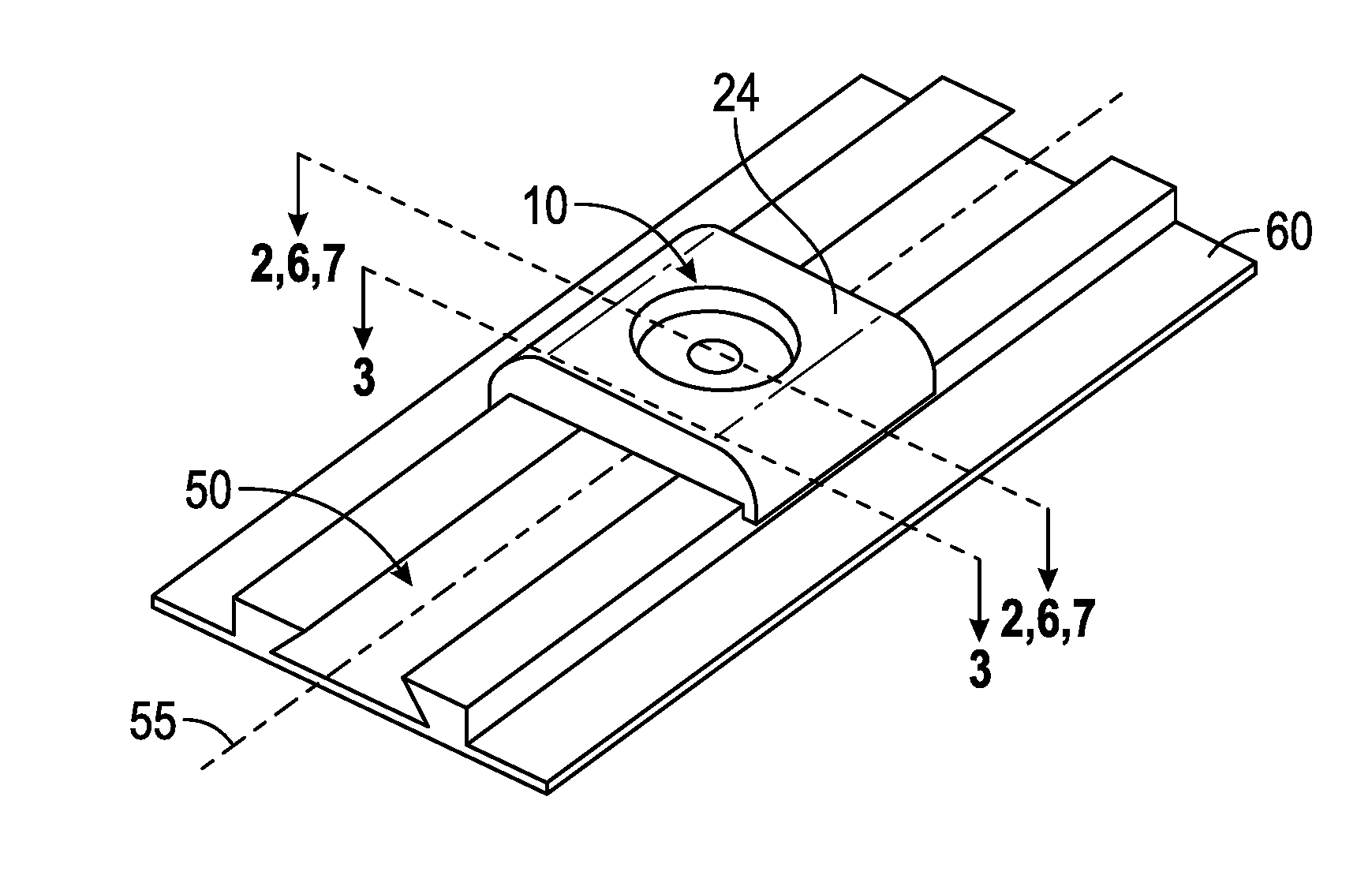
[0038]The design approaches described herein are based on a construction used in a driver head characterized by a composite crown adhesively bonded to a cast titanium body. This particular construction approach permits the crown configuration to be adapted to the inventive weighting scheme with minimal impact on weight and function. However, the weighting embodiments disclosed herein can be used with other constructions, including all titanium, all composite, and a composite body with metal face cup. It can also work in conjunction with at least one adjustable weight port on the sole of the driver head. Shifting weight along the channel described herein allows for control of center of gravity location. The slidable weight assembly 10 of the present invention can be used with any sporting goods equipment having a channel, but preferably is used with golf clubs such as woods, irons, putters, and hybrids.

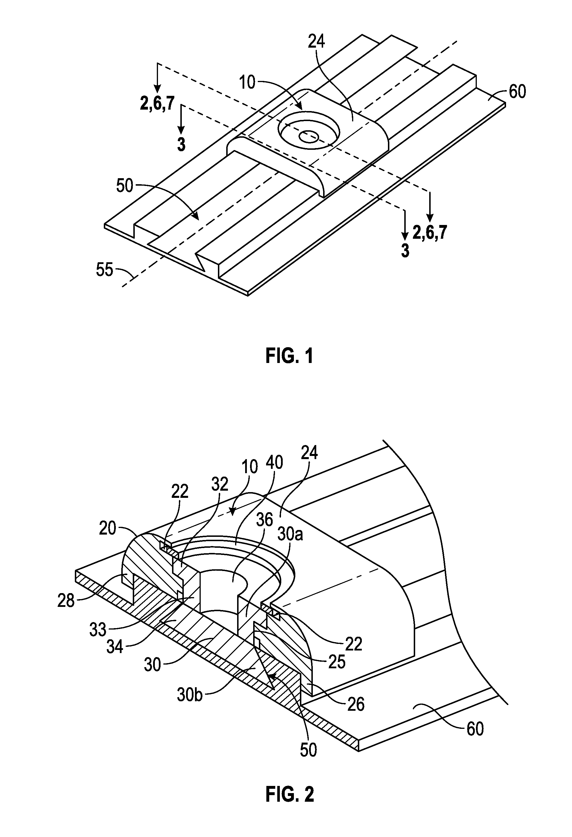
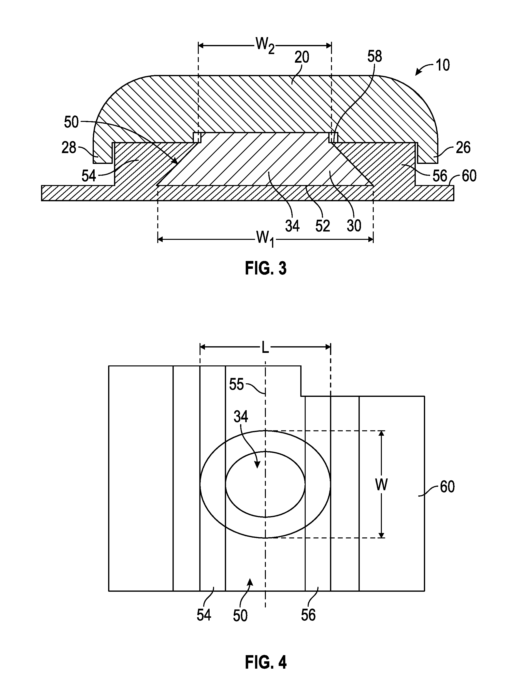
[0039]A first embodiment of the slidable weight assembly 10 of the present inventi...


PUM


Abstract

A golf club head comprising a channel or a pair of parallel rails and a slidable weight assembly that can be removably fixed at any point within the channel or to the rails is disclosed herein. The slidable weight assembly preferably comprises a weight portion and base that can be turned 45 to 90 degrees to reversibly fix the slidable weight assembly within the channel or to the rails.

Description

CROSS REFERENCES TO RELATED APPLICATIONS[0001]The present application is a continuation of U.S. patent application Ser. No. 14 / 216,971, filed on Mar. 17, 2014, and issued on Jul. 12, 2016, as U.S. Pat. No. 9,387,376, which claims priority to 61 / 940,288, filed on Feb. 14, 2014, and is a continuation-in-part of U.S. patent application Ser. No. 14 / 153,722, filed on Jan. 13, 2014, and issued on Dec. 1, 2015, as U.S. Pat. No. 9,199,145, which is a continuation of U.S. patent application Ser. No. 14 / 033,218, filed on Sep. 20, 2013, and issued on Apr. 15, 2014, as U.S. Pat. No. 8,696,491, which is a continuation-in-part of U.S. patent application Ser. No. 13 / 923,571, filed on Jun. 21, 2013, and issued on Jul. 21, 2015, as U.S. Pat. No. 9,084,921, which is a continuation-in-part of U.S. patent application Ser. No. 13 / 778,958, filed on Feb. 27, 2013, and issued on Nov. 25, 2014, as U.S. Pat. No. 8,894,506, which claims priority to U.S. Provisional Patent Application No. 61 / 727,608, filed on ...

Claims


Application Information

Patent Timeline
Patent Type & Authority Applications(United States)
IPC IPC(8): A63B53/06A63B60/52A63B53/04
CPCA63B53/06A63B53/0466A63B2053/0433A63B2053/0491A63B60/52A63B53/045A63B53/0433
Inventor HALL, J. NEILMYERS, MATTHEW
Owner TOPGOLF CALLAWAY BRANDS CORP
Why Eureka
Try Eureka